


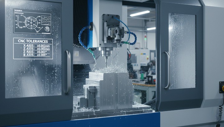
CNC machining tolerances determine whether your parts fit and function correctly. Many engineers struggle because tolerance selection affects not only accuracy and reliability, but also production cost, lead time, and supplier capability. Misjudging a single dimension can cause assembly failures, unnecessary rework, or over-engineered parts that cost far more to manufacture than needed.
This guide gives you a clear, practical framework to choose the right tolerances and functional fits—helping you design parts that assemble smoothly, perform consistently, and stay within budget.
Why Tolerances Matter in CNC Machining?
CNC machining tolerances define how much a feature may vary from its nominal dimension, and they directly influence part performance, assembly behavior, and manufacturing cost. When you select the right tolerance range, you support consistent functionality and avoid unnecessary rework. When tolerances are tighter than required, machining cost, lead time, and inspection effort increase quickly. Because CNC tolerances affect every stage of production—from toolpath programming to final assembly—you need a clear understanding of how tolerance decisions shape quality and budget.
The Role of Tolerances in Functional Performance, Cost, and Assembly
Tolerances determine whether CNC-machined parts fit, move, and operate as intended. When you choose the right machining tolerance
Tolerances significantly influence machining cost. Tight tolerances require slower feeds, more tool changes, and increased inspection frequency. Each incremental reduction in tolerance—such as moving from ±0.05 mm to ±0.01 mm—raises cost because the machine must remove less material per pass and verify each step. Balancing cost and precision protects your budget while maintaining functional performance.
Assembly quality depends heavily on predictable manufacturing tolerances. When parts fall within defined limits, you avoid binding, wobbling, or misalignment. Below are the key impact areas of CNC machining tolerances:
• Functional performance — alignment, smooth operation, controlled motion
• Cost control — machining time, inspection cycles, tool life
• Assembly reliability — predictable fits, reduced adjustments, stable interfaces
These points show why tolerances sit at the core of every CNC design and why choosing proper standard machining tolerances supports both performance and production efficiency.
Why Engineers Struggle With Specifying the Right Tolerance?
Engineers often struggle to choose tolerances because each tolerance depends on multiple interacting factors—functional requirements, material properties, machining capability, and geometric complexity. Many designers tighten tolerances “just to be safe,” which increases cost and may exceed practical machine tolerance capability. Others specify tolerances too loosely, resulting in clearance issues or inconsistent assembly.
Another challenge is supplier variation. Not all CNC shops can hold the same CNC machining tolerances. One facility may maintain ±0.01 mm repeatably, while another may achieve only ±0.05 mm depending on equipment age, environmental stability, or operator experience. Without early communication, tolerance expectations may not match real-world machining capability.
Here are the most common reasons engineers struggle:
• Difficulty balancing functional fit and cost
• Material expansion or deformation during machining
• Limited understanding of GD&T symbols such as flatness, position, and concentricity
• Underestimating tolerance stack-up across assemblies
• Misalignment between design intent and supplier capability
Handling these factors early allows you to define tolerances that protect function without increasing cost unnecessarily.
Functional Fits vs. Dimensional Tolerances — The Foundation of Precision Design
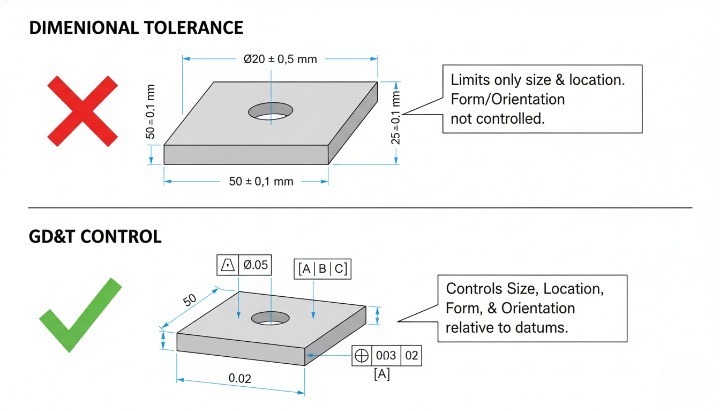
Functional fits describe how two components relate during assembly—whether they should slide freely, assemble snugly, or press together tightly. Dimensional tolerances define acceptable variation for individual features such as hole diameters or shaft lengths. Together, functional fits and dimensional tolerances create predictable, high-performing CNC assemblies.
Below is a clear comparison of the major tolerance categories:
| Type | Purpose | Common Application |
|---|---|---|
| Functional Fit | Defines clearance, transition, or interference behavior | Shafts, holes, bushings, bearings |
| Dimensional Tolerance | Controls acceptable variation of a single feature | Diameters, lengths, grooves |
| GD&T Control | Ensures geometric accuracy such as flatness or position | Precision CNC mating interfaces |
This table highlights how each tolerance type supports different aspects of CNC machining precision. When you combine functional fits with the correct machining tolerances, you create reliable assemblies that resist misalignment, vibration, and unexpected friction.
By aligning CNC machining tolerances with functional requirements, you strengthen performance, reduce cost, and improve repeatability across production runs.
What Are CNC Machining Tolerances?
CNC machining tolerances define the allowable dimensional variation for a machined feature, and they determine whether a part will fit, move, and perform as intended. When you establish clear tolerances, you help control precision, guide manufacturability, and set expectations for both machining capability and inspection. Because CNC machining tolerances, machine tolerance, and standard machining tolerances in mm directly influence part quality, every engineer should understand these concepts before finalizing a drawing.

Basic Tolerance Concepts
CNC machining tolerances describe the acceptable difference between the nominal dimension and the actual measurement. You use tolerances to ensure that parts fit consistently and meet their functional purpose. A well-defined tolerance range protects you from excessive variation that could cause binding, misalignment, or premature wear. Tolerances also inform the shop how precise the machining process must be, which affects cutting paths, inspection frequency, and cost.
To make these concepts easier to scan, here are the foundational ideas engineers rely on when defining machining tolerances:
• Nominal dimension — the target measurement shown on the drawing
• Upper and lower limits — the maximum allowable deviation from nominal
• Tolerance zone — the full range between limits
• Precision level — how tight or loose the tolerance band is
You can think of tolerances as the bridge between perfect design intent and the realistic capability of CNC equipment. A tolerance range that is too tight increases machining difficulty. A range that is too loose may compromise function. The correct balance helps you control performance and cost.
Dimensional vs. Geometric Tolerances
Dimensional tolerances define how far a feature may vary in size, while geometric tolerances (GD&T) define how a feature must relate to other features in shape, orientation, or position. You need both types to communicate complete design intent in CNC manufacturing. Dimensional tolerances ensure the right sizes; GD&T ensures the right relationships.
Below is a concise comparison that helps clarify how these two systems support precision:
| Tolerance Type | What It Controls | Examples |
|---|---|---|
| Dimensional Tolerance | Size and allowable variation | ±0.05 mm on diameter; ±0.1 mm on length |
| Geometric Tolerance | Shape, orientation, and feature relationships | Flatness, position, concentricity |
| Combined Use | Both size and geometry for functional performance | Shafts, housings, sealing interfaces |
Common Terminology Engineers Must Know
Engineers encounter many tolerance-related terms in CNC drawings, inspection reports, and machining guidelines. Understanding these terms helps you specify tolerances correctly and communicate clearly with suppliers. While different industries follow different standards, the following terms consistently appear in CNC machining, including Protolabs tolerances, standard machining tolerances, and general tolerancing references.
Below are essential tolerance terms, presented concisely for quick scanning:
• Bilateral tolerance — variation allowed in both positive and negative directions
• Unilateral tolerance — variation allowed only in one direction
• Limit tolerance — shows maximum and minimum values directly
• Fit class — describes assembly behavior (clearance, transition, interference)
• Tolerance stack-up — accumulated variation across multiple features
• Feature control frame (FCF) — GD&T symbol box defining geometric control
• Datum — reference feature for measurement or alignment
These terms shape every decision involving tolerance in production, manufacturing tolerance, and CNC machining precision. When you understand this terminology, you reduce miscommunication, avoid incorrect assumptions, and ensure your CNC supplier interprets your intent accurately.
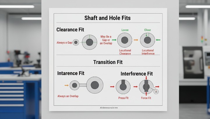
Understanding Functional Fits — Clearance, Transition, and Interference
Functional fits define how two CNC-machined parts assemble and move relative to each other. When you choose the correct fit class—clearance, transition, or interference—you control motion, load transfer, friction, and stability. Because functional fits, CNC machining tolerances, and tolerances in manufacturing directly shape real-world performance, they form the foundation of precision engineering and influence every tolerance decision.
How Functional Fits Control Assembly Behavior?
Functional fits determine how tightly two mating features—usually a shaft and hole—engage during assembly. The difference between their tolerances creates the “fit” that guides movement or locking strength. You improve reliability and reduce assembly issues when you choose the correct fit for the intended mechanical behavior. Functional fits help you manage everything from smooth rotation in bearings to rigid, load-bearing joints in structural components.
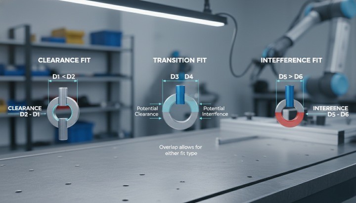
Here are the core functional fit types used in CNC machining:
• Clearance fit — always leaves space between parts; ideal for rotation or sliding
• Transition fit — sometimes loose, sometimes tight; ideal for alignment and stability
• Interference fit — parts are intentionally larger/smaller for press-fit or permanent locking
Clearance fits support free motion. Transition fits create a controlled, snug engagement. Interference fits create permanent mechanical bonding. Each fit responds differently to dimensional variation, surface finish, and machining tolerance capability. When you choose a fit that matches the function, you reduce friction, improve assembly repeatability, and prevent mechanical failure.
Functional fit selection becomes especially important in high-precision CNC applications where tolerances may fall within ±0.01 mm or tighter. Because machine tolerance, CNC machine precision, and tighter tolerances directly influence achievable fits, you must align fit intent with real machining capabilities early in the design process.
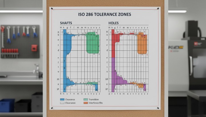
ISO 286 Fit Classes Explained
ISO 286 provides the internationally recognized system for fit tolerances between shafts and holes. The standard groups fits into standardized classes—each defining acceptable variation ranges for clearance, transition, or interference behavior. You can use these fit classes to define consistent tolerancing across suppliers, regions, and industries.
A simplified overview of ISO 286 fit categories appears below:
| Fit Type | ISO 286 Examples | Behavior |
|---|---|---|
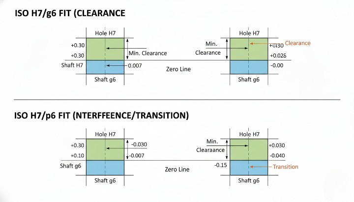
| Clearance Fit | H7/g6, H8/f7 | Always leaves space; supports rotation |
| Transition Fit | H7/k6, H7/js6 | Snug or lightly tight; supports alignment |
| Interference Fit | H7/p6, H7/u6 | Always tight; supports press-fit assemblies |
This table helps you compare different fit types at a glance. ISO tolerance letters indicate hole basis (H) or shaft basis (g, f, k, p, u, etc.), while the numbers indicate tolerance grades. Lower numbers represent tighter machining tolerances. When you follow ISO 286, you ensure that parts machined in different locations will assemble consistently without adjusting drawings or modifying tooling.
Engineers often reference ISO fits along with machining tolerance chart, standard machining tolerances, and tolerancing standards to predict achievable precision based on CNC capability. Matching an ISO fit class with realistic shop tolerances helps avoid out-of-tolerance parts, misalignment, and assembly delays.
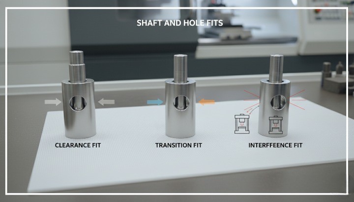
Real Engineering Examples of Functional Fits in CNC Parts
Functional fits appear across industries—from automotive shafts to medical device housings—and each example shows how tolerance decisions influence performance. When you specify the right functional fit, you prevent friction, wear, or unwanted movement. When the fit is incorrect, parts either seize or feel unstable.
Below are practical examples that demonstrate how engineers apply clearance, transition, and interference fits in CNC-machined components:
• Clearance Fit (H7/g6) Used for motor shafts, gears, or pulleys that require smooth rotation. The clearance prevents binding and reduces heat buildup, especially in high-speed CNC-machined assemblies.
• Transition Fit (H7/k6) Used for dowel pins or locating features that require precise alignment without excessive force. This fit supports stable positioning in equipment frames, brackets, and robotic joints.
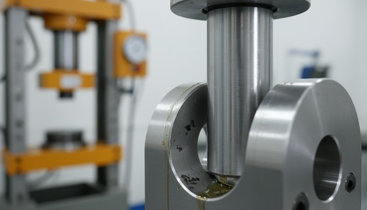
• Interference Fit (H7/p6 or H7/u6) Used for press-fit bearings, structural couplings, and high-pressure components. The tight engagement ensures zero slip under load and prevents micro-movement that can cause fatigue failure.
These examples show how functional fits guide design decisions related to tolerance in production, manufacturing tolerance, precision CNC machined
Standard CNC Machining Tolerances

Standard CNC machining tolerances define the precision level you can expect from CNC milling and turning. When you understand typical machining tolerances, you design parts that meet functional requirements without increasing cost. Because every feature behaves differently under cutting forces, heat, and tool deflection, you need a clear understanding of standard machining tolerances, CNC tolerances, and machining tolerance charts to make informed design decisions.
Typical Tolerances Achievable by CNC Milling and Turning
CNC milling and CNC turning reach different precision levels because each process handles geometry and cutting forces in its own way. Milling supports complex shapes, but long tools reduce accuracy. Turning provides better concentricity, so it supports tighter CNC machine tolerance values on shafts and round features.
Below are typical precision levels engineers reference when planning CNC machining tolerances:
CNC Milling Tolerances
• Standard features: ±0.10 mm to ±0.05 mm
• Precision features: ±0.02 mm to ±0.01 mm
• High-accuracy milling: ±0.005 mm (for critical fits)
CNC Turning Tolerances
• Standard diameters: ±0.05 mm to ±0.02 mm
• Precision shafts: ±0.01 mm to ±0.005 mm
• Ultra-tight tolerance turning: ±0.003 mm
These values reflect real machining capability across modern shops and align with published ranges from well-known providers such as Protolabs machining, Protolabs CNC machining, and other online CNC platforms. You can use these bands to determine whether a feature requires general machining, tight-tolerance machining, or processes such as grinding or EDM.
Standard Machining Tolerances in Metric and Inch
You may work with suppliers who follow ISO 2768 (metric general tolerances) or ASME standards. These standards guide standard machining tolerances in mm and inch when a drawing does not specify an exact value. They serve as default limits for non-critical surfaces and simplify communication across global teams.
| Nominal Dimension | Standard Machining Tolerance (mm) | Standard Machining Tolerance (inch) |
|---|---|---|
| 0–30 mm | ±0.10 mm | ±0.004 in |
| 30–120 mm | ±0.15 mm | ±0.006 in |
| 120–400 mm | ±0.20 mm | ±0.008 in |
| 400–1000 mm | ±0.30 mm | ±0.012 in |
These default values help you design faster by providing a baseline for manufacturing tolerance and general tolerancing. When a feature controls movement, sealing, or alignment, you must avoid relying on general tolerances and instead assign engineering-specific limits.
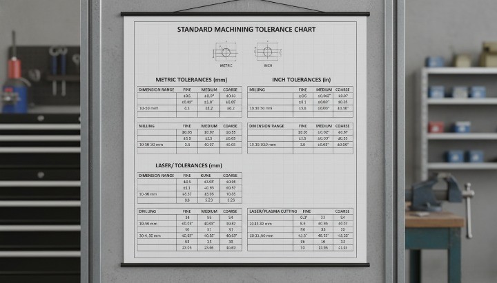
CNC Machining Tolerance Chart
A machining tolerance chart helps you compare capabilities across different processes. Each machining method delivers its own tolerance window depending on tool rigidity, heat control, fixturing, and material response.
| Process | Typical Tolerance Range | Notes |
|---|---|---|
| CNC Milling | ±0.10 mm to ±0.01 mm | Tool length affects accuracy |
| CNC Turning | ±0.05 mm to ±0.005 mm | Excellent for concentricity and shafts |
| EDM Machining Tolerances | ±0.005 mm to ±0.002 mm | Ideal for tight tolerance machining |
| Laser Cutting Tolerance | ±0.20 mm to ±0.10 mm | Depends on thickness and heat input |
| CNC Plasma Cutter Tolerances | ±0.50 mm to ±0.25 mm | Suitable for low-precision components |
This overview shows where CNC milling and turning fit relative to other manufacturing methods. When your drawing requires tolerances tighter than these ranges, processes like grinding, honing, or lapping may become necessary.
What Is the Standard Tolerance for CNC Machining?
Most manufacturers follow a baseline standard tolerance when a drawing does not specify one. These values represent widely accepted industry defaults and match what you see from digital manufacturers, traditional machine shops, and services such as Protolabs tolerances, tolerances in manufacturing, and online CNC machining platforms.
Standard tolerance levels include:
• ±0.10 mm (±0.004 in) — general CNC machining
• ±0.05 mm (±0.002 in) — standard precision CNC machining
• ±0.01 mm (±0.0004 in) — tight tolerance machining
These ranges define what most suppliers can produce consistently during standard production. Final capability depends on part geometry, material, fixturing, and machine calibration. You always improve manufacturability when you share tolerance-critical features early and confirm the supplier’s exact CNC machining tolerances capability.
These standard machining tolerances help you balance performance, cost, and manufacturing efficiency—while keeping your CNC part both functional and repeatable.
Factors That Affect Achievable Tolerances
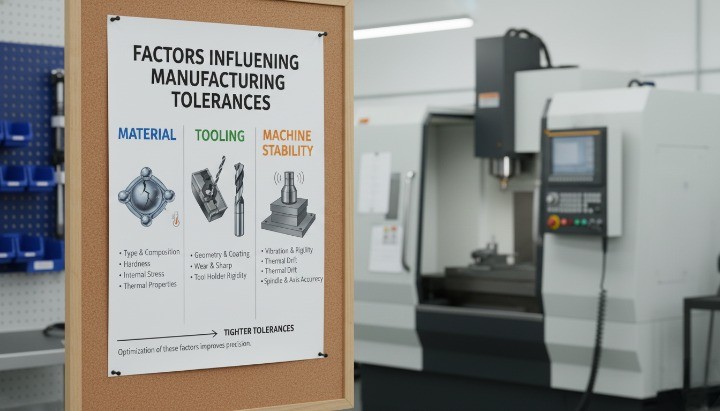
Achievable CNC machining tolerances depend on more than machine capability. Every material, geometry, and cutting condition influences the final accuracy you can hold. When you understand these variables, you design parts that align with real manufacturing limits instead of idealized conditions. The following sections explain the major factors that determine whether your parts achieve tight tolerance machining, general tolerances, or require secondary processes.
Material Machinability
Material properties have a strong influence on the tolerance range you can achieve. Some materials cut cleanly and maintain dimensional stability. Others deflect, harden, or generate heat during machining, which reduces accuracy. You improve your results when you match tolerance needs to realistic manufacturing tolerance capabilities for each material.
Key material behaviors that influence tolerance:
• Hardness — Hard metals like stainless steel resist cutting and create tool wear, which shifts dimensions.
• Elasticity — Soft materials like plastics flex under the cutting load, reducing accuracy.
• Thermal expansion — Aluminum heats quickly, expanding during machining and shrinking at rest.
• Work hardening — Titanium and certain steels harden at the cutting zone, affecting repeatability.
Below is a summary of typical tolerance behavior by material.
| Material Type | Machinability Impact | Typical CNC Tolerance Range |
|---|---|---|
| Aluminum (6061/7075) | Excellent machinability | ±0.05 mm to ±0.01 mm |
| Stainless Steel (304/316) | Work hardening, higher tool wear | ±0.10 mm to ±0.02 mm |
| Brass & Copper | Stable, clean cutting | ±0.04 mm to ±0.01 mm |
| Titanium | Thermal issues, work hardening | ±0.10 mm to ±0.03 mm |
| Plastics / Thermoplastics | High elasticity, heat sensitivity | ±0.20 mm to ±0.05 mm |
When you design with tight tolerances on challenging materials, you may need processes such as grinding or EDM to achieve the required accuracy.
Part Geometry
The geometry of your CNC part determines whether tight tolerances are realistic. Long, thin, or deep features cause tool deflection and vibration. Complex surfaces may require multi-axis movement, which increases tolerance variation. You improve accuracy by designing with shorter tool reach, stable wall thickness, and uniform geometry.
Geometric features that reduce achievable tolerance:
• Deep pockets
• Thin walls
• Long shafts or rods
• Large flat surfaces that warp
• Internal corners with tight radii
Complex geometry often requires slower toolpaths, more setups, and more inspection steps. These factors raise cost and influence the final tolerance you can hold.
Machine Capability and Tool Performance
The performance of the CNC machine and cutting tools plays a major role in your achievable tolerance. Older machines may not maintain micrometer-level accuracy, while modern 4-axis and 5-axis machines deliver tighter positioning control.
Machine-related factors that influence tolerance:
• Machine rigidity and age
• Spindle accuracy and runout
• Thermal stability and cooling systems
• Tool wear and tool material selection
• Fixturing stability
Machines that support high-precision work often feature thermal compensation systems and advanced measurement probes. These tools allow suppliers to consistently achieve tight tolerance machining levels such as ±0.01 mm or better.
Tool performance matters just as much. Dull or mismatched tools cause chatter and dimensional drift. When tools wear unevenly, tolerance consistency drops, especially in long production runs.
Surface Finish Requirements
Surface finish and tolerance are closely linked. High-quality finishes require slower cutting speeds, finer tools, and more stable conditions—all of which influence the final tolerance range.
Examples of how finish influences tolerance:
• A requirement of Ra 0.8 μm typically reduces machinable tolerance by 30–50%.
• Polished or ground surfaces may need a secondary finishing step.
• Hard materials with tight finishes often require special tooling.
When you need both a fine finish and a tight tolerance, you must communicate this early because these two requirements often increase machining time and cost.
Machining Environment and Operator Skill
Even the best machine cannot achieve tight tolerances without controlled environmental conditions. Temperature changes create expansion differences in both the machine and the workpiece. Skilled operators understand how to compensate for these effects, adjust toolpaths, and inspect critical features.
Environmental and human factors include:
• Shop temperature control
• Vibration and noise from surrounding machines
• Calibration and measurement routines
• Operator experience with high-precision work
• Inspection technique and coordinate measuring machine (CMM) quality
Shops that specialize in high tolerance machining often maintain climate-controlled rooms, invest in precision inspection equipment, and follow strict tool calibration procedures.
When you understand these five factors—material machinability, part geometry, machine capability, surface finish needs, and operator skill—you create tolerance requirements that match real CNC machining conditions. This approach reduces risk, improves consistency, and helps you achieve the exact CNC machining tolerances your project requires.
Types of Tolerancing Systems Used in CNC Machining

You control CNC machining tolerances using several tolerancing systems. Each system defines allowable dimensional variation in a different way. When you choose the correct system, you communicate design intent clearly and help your machining supplier deliver consistent, accurate, and cost-effective parts. The sections below explain the four most common systems: standard tolerances, limit tolerances, unilateral and bilateral tolerances, and GD&T tolerances. These concepts form the foundation of modern engineering drawings and influence everything from fit quality to machining cost.
Standard Tolerances
Standard tolerances give you default dimensional limits when a drawing does not specify individual values. Many industries follow ISO 2768 for general machining tolerances, which helps speed up engineering drawings and ensures consistent interpretation.
These standard systems define tolerance classes such as ISO 2768-m (medium) or ISO 2768-f (fine). You typically use them for non-critical dimensions where exact precision is not required.
Key points about standard tolerances:
• They apply automatically to all unspecified dimensions.
• They help reduce clutter on engineering drawings.
• They support features like non-critical lengths, widths, and hole locations.
Typical ISO 2768 ranges for metal CNC machining:
| ISO Class | General Dimensional Range | Typical Tolerance |
|---|---|---|
| f (fine) | 0.5–120 mm | ±0.05 to ±0.2 mm |
| m (medium) | 0.5–400 mm | ±0.1 to ±0.5 mm |
| c (coarse) | 1–1000 mm | ±0.5 to ±1.5 mm |
Because standard tolerances cover non-critical areas, they save time and lower machining cost without affecting functional performance.
Limit Tolerances
Limit tolerances define the upper and lower dimensional limits directly, rather than expressing variation from a nominal dimension. They appear as two values—for example, 12.70 / 12.65 mm—and tell the machinist exactly how far the feature can vary.
You use limit tolerances when the acceptable dimensional range must be clear and unambiguous. Many machining tolerance charts and supplier guidelines also use this format because it offers direct boundaries.
Advantages of limit tolerances:
• Clear maximum/minimum limits
• Minimal interpretation risk
• Ideal for mating parts such as pins and holes
• Supports high-precision CNC and EDM machining work
Limit tolerances are common in industries that require strict assembly control, such as aerospace, robotics, and medical devices.
Unilateral and Bilateral Tolerances
Unilateral and bilateral tolerances define how the dimension may vary relative to the nominal value. You choose between them based on functional intent, machining capability, and risk of interference.
Unilateral tolerances allow variation in only one direction—for example:
• 10.00 mm +0.00 / –0.05 mm
• 25.00 mm +0.10 / +0.00 mm
You normally use unilateral tolerances when a feature must never exceed a limit. Holes often use negative unilateral tolerances, while shafts may use positive unilateral tolerances.
Bilateral tolerances allow variation in both directions—for example:
• 20.00 ± 0.05 mm
• 8.00 ± 0.02 mm
Bilateral tolerances work best for symmetric fits or when the machining process can hold variation evenly above and below the nominal dimension.
Key differences:
| Tolerance Type | Variation Direction | Typical Use Case |
|---|---|---|
| Unilateral | One-direction variation | Holes, shafts, sealing areas |
| Bilateral | Variation above and below nominal | General machining dimensions |
Choosing the correct tolerance direction helps you avoid interference, ensure clearance, and maintain predictable assembly behavior.
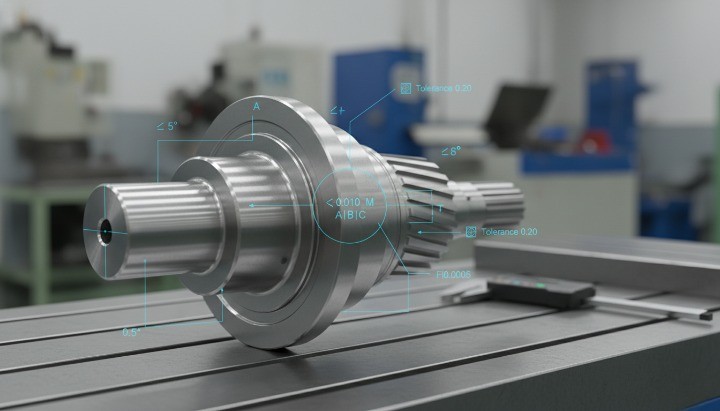
GD&T Tolerances and Proper Use Cases
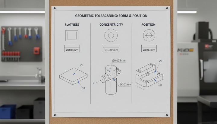
GD&T (Geometric Dimensioning and Tolerancing) expands beyond simple size control. It defines geometric relationships that influence function, shape, and alignment. You apply GD&T when size tolerances alone cannot guarantee performance.
Common GD&T controls include:
• Flatness — Ensures surfaces remain uniformly level
• Position — Controls true location of holes and features
• Concentricity — Aligns cylindrical features for smooth rotation
• Cylindricity — Defines uniform diameter across the entire feature
• Perpendicularity / Parallelism — Ensures proper alignment in assemblies
You use GD&T when:
• Features interact during motion
• Holes must align for fasteners or shafts
• Rotational components require smooth operation
• High-precision CNC tolerances must be repeatable
• Tolerance stack-up could cause assembly failure
GD&T also helps reduce cost when used correctly. For example, a position tolerance often replaces an overly tight ±0.01 mm dimensional tolerance. This approach focuses on function rather than arbitrary precision, which supports more efficient machining.
When you understand how standard tolerances, limit tolerances, unilateral and bilateral tolerances, and GD&T tolerances work together, you communicate design intent clearly and improve manufacturability. Each system supports different aspects of CNC machining tolerances and helps you deliver parts that fit, function, and assemble reliably across every production run.
Tolerancing Guidelines for Functional Fits

Functional fits determine how CNC-machined components behave during assembly, and they strongly influence motion control, load transfer, and long-term reliability. When you apply clear tolerancing guidelines, you create CNC parts that align correctly, maintain performance, and remain cost-efficient. Because CNC machining tolerances, manufacturing tolerance, and tolerances in drawings shape your product’s precision, you need a structured approach to define each level of accuracy.
Choosing the Correct Functional Fit Based on Application
You select a functional fit by focusing on how two mating features must interact. A correct fit prevents binding, reduces vibration, and protects durability. You consider fit type—clearance, transition, or interference—based on the application’s mechanical demands and how the chosen machining tolerances influence assembly.
Key factors that guide your fit choice include:
• Movement requirements — sliding, rotation, positioning
• Load demands — torque transfer, static loads, shock resistance
• Thermal expansion — relevant when mixing mm CNC aluminum and steel parts
• Maintenance frequency — ease of disassembly vs permanent joints
• Environmental forces — vibration, lubrication, moisture, temperature
Below is a concise comparison table to help you match the correct fit type with functional behavior. It includes bolded keywords to support your tolerance-related search relevance:
| Fit Type | Assembly Behavior | Typical Use |
|---|---|---|
| Clearance Fit | Always leaves space; relies on loose CNC tolerances | Bearings, sliding rails, general CNC parts |
| Transition Fit | Allows light press or slip; depends on machining tolerance ranges | Locating pins, couplings, alignment bosses |
| Interference Fit | Requires force; depends on precise tolerances in manufacturing | Gears, pulleys, high-load rotating systems |
When you design for performance, you match functional behavior to tolerance capability rather than forcing unnecessary precision.
How Tight Is Tight Enough?
You determine “tight enough” based on functional needs, not arbitrary preference. Extremely tight machine tolerances increase costs and slow production, especially on parts with complex geometry or sensitive materials. A balanced approach ensures you hit the performance target without burdening manufacturing.
General tolerance guidelines in CNC machining:
• Standard features: ±0.10 mm
• Precision mechanical fits: ±0.05 mm
• High-precision shafts/bores: ±0.01–0.02 mm
• Ultra-tight features: ±0.005 mm
These ranges align with common values used across global platforms such as Protolabs tolerances, Protolabs machining, and Protolabs CNC machining. You reserve the tightest ranges for tight tolerance machining, sealing interfaces, and high-speed rotating components.
Features that typically require tighter tolerances:
• Bearing seats
• Precision holes and patterns
• Alignment pins
• Press-fit housings
• Critical sealing surfaces
Features that rarely require tight tolerances:
• Outer profiles
• Brackets and supporting plates
• Non-critical lengths or widths
• Cosmetic surfaces
By matching tolerance levels to functional importance, you maintain precision while protecting cost.
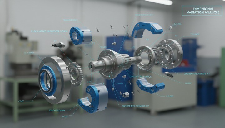
Tolerance Stacking Considerations
Tolerance stack-up occurs when small dimensional variations add up across multiple features, and it can cause assemblies to drift out of alignment even when individual features meet their standard machining tolerances. You maintain accuracy by controlling your datum scheme and using GD&T tolerancing only where necessary.
Common risks created by stack-ups include:
• Misaligned hole patterns
• Shaft/housing centerline drift
• Increased mechanical play
• Fixture distortion
Effective strategies that reduce tolerance stack-up:
• Reference critical features to datums
• Use GD&T position instead of many independent dimensions
• Apply tighter CNC machining tolerances only where needed
• Minimize dimension chains by redesigning geometry
A structured comparison helps clarify the effect of different stack-up approaches:
| Approach | Impact on Assembly Accuracy |
|---|---|
| Many independent dimensions | Highest stack-up error |
| Datum-based dimensions | Predictable alignment with reduced variation |
| GD&T position control | Most stable and functional alignment |
Managing stack-up ensures your assemblies remain precise even when parts come from different batches or suppliers.
When Not to Specify Tight Tolerances?
You avoid tight tolerances when a feature does not influence function, alignment, or long-term stability. Over-tolerancing increases cost, complicates inspection, and may extend lead time—especially on close tolerance machining or complex precision CNC machined parts.
Avoid tightening tolerances in these situations:
• Cosmetic or non-functional surfaces
• Outer edges or profiles that do not align with other parts
• Areas with large material removal or deep pockets
• Regions prone to thermal deformation
• Surfaces with no contact requirements
• Features already covered by general standard tolerancing
Examples of dimensions that seldom require tight tolerance:
• Housing outlines
• Simple slots or tabs
• Cover plates
• Decorative chamfers
• Non-critical mounting holes
By tightening tolerances only where necessary, you protect both performance and cost while maintaining manufacturability.
How Tolerances Influence Machining Cost?
CNC machining tolerances have a direct and measurable impact on manufacturing cost. When tolerance bands tighten, machining becomes slower, inspection becomes more intensive, and scrap risk increases. Because CNC machining tolerances, standard machining tolerances, and tight tolerance machining define how much variation a part can accept, you must balance precision with budget. A practical tolerance strategy helps you protect performance without inflating cost.
Why Tighter Tolerances Increase Cost?
You see cost rise quickly when tolerances move from standard ranges to high-precision or ultra-tight levels. This cost increase occurs because the machining process must remove smaller amounts of material, adjust toolpaths more frequently, and repeat inspections to hit extremely narrow tolerance windows.
Primary cost drivers include:
• Slower machining speeds — tight machining tolerances require light cuts and reduced feed rates.
• More tool wear — precision cuts accelerate wear, especially in hard metals.
• Frequent in-process inspection — CMM checks increase cycle time.
• Specialized fixtures — precision alignment often needs custom jigs or clamps.
• Higher rejection rates — reduced tolerance ranges raise the chance of out-of-tolerance parts.
To illustrate how tolerance choices influence cost and feasibility, the table below summarizes typical ranges and their effect on production. Keywords are naturally embedded for SEO relevance.
| Tolerance Range | Description | Cost Impact |
|---|---|---|
| ±0.10 mm (standard machining tolerances) | Good for general CNC parts | Lowest cost |
| ±0.05 mm (precision CNC machining tolerances) | Suitable for functional fits | Moderate cost |
| ±0.01–0.02 mm (tight tolerance machining) | Needed for shafts, bores, sealing features | High cost |
| ±0.005 mm and below (ultra-tight) | Requires optimized setups or EDM machining tolerances | Extremely high cost |
This progression shows how tolerances influence both process complexity and budget.
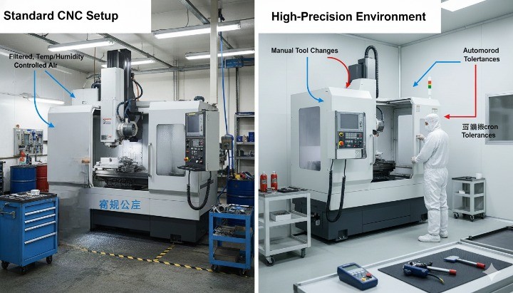
Low-Cost vs High-Precision CNC Setups
Different CNC setups support different tolerance levels, and choosing the right setup controls your cost. Standard 3-axis machining handles most typical machining tolerances, while complex or tight tolerances often require more advanced machines.

Low-cost setups typically include:
• 3-axis milling machines
• Standard-quality toolholders
• Conventional end mills
• Basic fixturing
• Manual inspection tools (calipers, gauges)
These setups support most standard CNC machining tolerances at a competitive price.
High-precision setups require:
• 5-axis machining centers
• Shrink-fit or hydraulic toolholders
• Diamond or coated cutting tools
• Thermally stable machining environments
• CMM inspection for every critical feature
These setups deliver narrow machine tolerances, but each upgrade increases cost.
Practical Tolerance Selection Tips to Minimize Cost
You can reduce cost significantly when you apply tolerances strategically rather than uniformly across every feature. The most effective approach is to match tolerance levels to functional importance, machining capability, and inspection requirements.
Practical ways to reduce cost while maintaining function:
• Use standard machining tolerances in mm for non-critical features.
• Tighten tolerances only on features essential to functional fits.
• Apply GD&T flatness, position, or concentricity instead of overly tight size tolerances.
• Avoid chains of linear dimensions; use datums to reduce stack-up.
• Consider EDM machining tolerances only when geometry or sharp internal corners require it.
• Ask your supplier for DFM feedback early to confirm achievable tolerance levels.
To help you scan quickly, here is a concise decision guide:
| Design Objective | Recommended Tolerance Strategy |
|---|---|
| Reduce machining cost | Use standard tolerance ranges where possible |
| Improve assembly precision | Tighten tolerances only on mating features |
| Control geometric accuracy | Apply GD&T instead of narrow size limits |
| Minimize stack-up variation | Establish clear datum references |
| Improve cross-supplier stability | Use ISO-based tolerance classes and consistent callouts |
By applying these guidelines, you maintain performance without driving up cost unnecessarily.
Industry Use Cases Requiring Tight CNC Tolerances
Tight CNC machining tolerances support industries where safety, motion accuracy, sealing integrity, or repeatability determine whether a product performs reliably. You see these requirements in automotive, aerospace, robotics, and medical applications, where designers must specify tight tolerance machining, GD&T controls, and consistent standard engineering tolerances to ensure functional quality. Each industry uses precision differently, but all depend on predictable dimensional control.
Automotive Applications
Automotive components rely on precise tolerance control to ensure smooth motion, consistent wear patterns, and safe operation under high loads. Critical systems such as powertrains, braking assemblies, and steering modules depend on predictable fits between moving components. Engineers often apply tight machining tolerances, GD&T concentricity, and stable datum structures to maintain consistent function throughout mass production.
You frequently see tight tolerances in the following areas:
• Shafts and housings that require transition or interference fits
• Engine components with strict positional tolerances
• Transmission gears requiring tight runout control
• Brake system parts that rely on precise flatness tolerances
These components rely on CNC machining processes that hold ±0.01–0.02 mm or better to ensure consistent performance over thousands of cycles. The automotive industry often selects materials such as steel or aluminum alloys, which support tighter machine tolerances due to predictable machinability and thermal behavior.
Aerospace Applications
Aerospace parts demand some of the most stringent machining tolerances in manufacturing. High stresses, temperature swings, and fatigue loads require materials and geometries that maintain alignment under extreme conditions. Because safety margins are low, designers use GD&T tolerancing, including flatness, perpendicularity, and true position, to verify geometric accuracy.
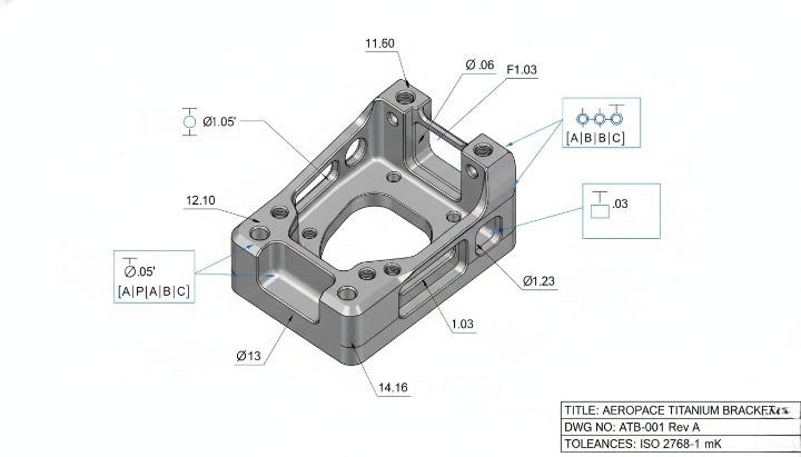
Examples of aerospace components requiring tight tolerances include:
• Turbine blade mounts and housings
• Flight-control linkage components
• Structural brackets and fixtures
• Fuel system connectors requiring precise clearance fits
Materials such as titanium, Inconel, and high-strength aluminum alloys challenge machining processes but deliver strength-to-weight performance. Because aerospace suppliers must document every dimension, CNC machining processes typically involve multi-step inspections, CMM verification, and thermal-controlled machining environments.
Robotics Applications
Robotics depends on smooth, predictable mechanical motion, meaning precision fits and accurate geometry are essential. Even minor misalignment can cause vibration, positioning errors, or premature wear. Robotics designers often combine standard machining tolerances for non-critical features with tight CNC tolerances on joints, bearings, and drive components.
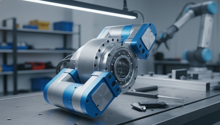
Common robotics parts requiring precision include:
• Servo motor housings and mating flanges
• Linear rail blocks and motion components
• Precision shafts requiring GD&T concentricity
• Arm joints that rely on consistent clearance or transition fits
Because robotic assemblies often stack multiple rotating and sliding interfaces, tolerance stack-up can quickly lead to drift or binding. Tight tolerance machining and geometric accuracy help maintain repeatability and smooth movement.
Medical Device Applications
Medical components require predictable fits, smooth surfaces, and strict dimensional accuracy because they interact with biological environments or precision diagnostic equipment. The industry often demands tight tolerance machining, controlled finishes, and consistent standard machining tolerances in mm to ensure reliability and patient safety.
Typical medical components requiring high precision include:
• Surgical tools and rotating shafts
• Implantable components requiring matched geometries
• Diagnostic equipment housings
• Pump components requiring consistent interference or transition fits
Because traceability matters, medical manufacturers inspect critical features using CMM, optical systems, or contact probes. Materials such as stainless steel, titanium, and engineering polymers (including close tolerance thermoplastic machining) require controlled toolpaths to maintain geometry and avoid heat distortion.
How to Properly Specify Tolerances?
Clear communication in engineering drawings ensures that CNC machining tolerances align with your functional needs, manufacturing goals, and cost targets. You guide the manufacturer when you specify standard machining tolerances, GD&T controls, and the correct functional fit for mating parts. Precise drawings reduce ambiguity and protect the intent behind each dimension. When you define tolerances consistently, suppliers can hold the correct CNC machine tolerance without overshooting cost or quality.
Where to Place Tolerances on Drawings?
Engineers place tolerances directly next to the controlled dimension, or within a general tolerance block when tolerances apply across the drawing. This placement helps you communicate priority and functional intent. You ensure clarity when critical dimensions include explicit tolerances, while secondary dimensions rely on standard tolerancing listed in the title block.
Important placement guidelines include:
• Add explicit tolerances to all critical-to-function (CTF) features
• Use general tolerances for non-critical features to avoid clutter
• Apply GD&T frames when geometric control matters more than size
• Place reference dimensions clearly to avoid interpretation issues
This structure helps machinists understand which areas hold tight tolerance machining requirements and which dimensions follow standard values such as ±0.10 mm or ±0.20 mm.
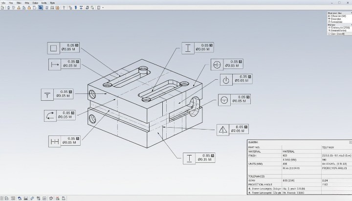
Combining Dimensional Tolerances With GD&T
You improve clarity when you combine dimensional limits with geometric controls. Dimensional tolerances define size variation, while GD&T tolerances—such as flatness, position, and concentricity—define the geometric behavior of features relative to datums. CNC machining suppliers depend on this combination to understand true functional intent.
Examples of effective combinations:
| Feature Type | Dimensional Control | GD&T Control | Purpose |
|---|---|---|---|
| Rotating shaft | ±0.01 mm tolerance | GD&T concentricity | Ensures smooth rotation |
| Mounting hole | Limit tolerance | GD&T position | Ensures assembly alignment |
| Sealing surface | ±0.02 mm | GD&T flatness | Ensures leak-free contact |
Combined tolerancing helps you avoid common issues such as dimensional compliance but geometric failure, which happens when a part meets size limits but cannot assemble correctly due to shape distortion.
Communicating Critical-to-Function Dimensions to Suppliers
You ensure manufacturability when you communicate which features matter most. Manufacturers allocate their process controls, tool choices, and inspection resources based on your priority list. When you identify critical tolerances, your supplier can apply more robust machining methods or inspection steps.
Ways to clearly communicate CTF dimensions:
• Highlight or flag critical dimensions using symbols or notes
• Share a tolerance priority list during RFQ or DFM review
• Provide mating-part data to explain functional fits
• Use callouts such as “Press-fit requirement” or “Slip-fit required”
Because suppliers may use different machining centers, providing context ensures they choose the right workflow—standard milling for moderate tolerances or tight tolerance CNC machining services for high-precision features.
Default Tolerances vs. Specified Tolerances
Most drawings include a default tolerance block that applies to unspecified dimensions. You save engineering time when you use defaults for non-critical features. However, relying only on default tolerances can cause assembly issues if functional fits require something tighter.
Typical default ranges include:
• ±0.10–0.20 mm for basic CNC milling
• ±0.05 mm for tighter standard machining
• ±0.01 mm or better for precision components
You should specify tolerances explicitly when you need consistent fit behavior, geometric alignment, sealing surfaces, or bearing seats. When you balance default tolerances with explicit ones, you ensure manufacturability while controlling cost.
Common Mistakes Engineers Make When Choosing Tolerances
You improve part performance and reduce machining cost when you avoid common tolerancing mistakes. Many designs fail or become unnecessarily expensive because tolerances do not reflect real functional needs, material behavior, or CNC machining tolerance capability. You can prevent rework and delays when you understand how each error affects manufacturability and assembly. These mistakes appear across industries—from automotive and robotics to medical components—because the same principles govern how machining tolerances influence function and cost.
Overusing Tight Tolerances
You risk increasing machining cost and lead time when you apply tight tolerances without a functional reason. Because tight tolerance machining requires slower feeds, refined toolpaths, more inspection, and sometimes specialized equipment, each unnecessary requirement adds cost. Many engineers apply ±0.01 mm tolerances “just to be safe,” but this approach can triple machining time and push parts into high-precision workflows.
Common problems caused by over-tolerancing:
• Increased scrap rates due to narrow tolerance windows
• Higher inspection cost and longer quality control cycles
• Need for premium machines or EDM to hold unrealistic limits
• Lead time extensions because of repeated adjustments
You protect both cost and manufacturability when you reserve strict tolerances for CTF (critical-to-function) features only.
Ignoring Functional Fit Requirements
Parts often fail during assembly when tolerances do not support the correct functional fit. For example, designers may apply standard tolerances to a press-fit bushing or over-tighten tolerances on a sliding shaft. Functional fits—clearance, transition, and interference—determine how two parts interact. When tolerances do not match the required fit, assemblies can bind, loosen prematurely, or vibrate.
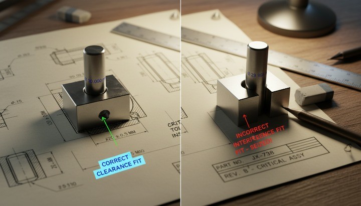
Common issues include:
• Clearance fits that become too tight and create friction
• Interference fits that are too strong and cause deformation
• Transition fits that fail to hold alignment
• Assemblies that drift because tolerances stack in the wrong direction
You create reliable assemblies when you choose tolerances based on ISO fit systems, not guesswork.
Misunderstanding Material Expansion or Deformation
Materials respond differently to machining forces, heat, and environmental changes. When you overlook these effects, tolerances that seem logical on paper fail in real-world use. Plastics, aluminum, and stainless steel behave differently during machining and in service, so tolerances must reflect these material characteristics.

Typical material-related mistakes:
• Applying metal-level tolerances to plastic parts
• Forgetting that thermoplastics deform under clamp pressure
• Ignoring thermal expansion in aluminum assemblies
• Overlooking spring-back in thin-wall features
This is especially important for close tolerance thermoplastic machining, where the material’s flexibility limits achievable precision. You avoid these issues when you match tolerance bands to material behavior rather than using one global tolerance.
Assuming All CNC Suppliers Can Hold the Same Tolerances
CNC shops vary widely in their equipment accuracy, spindle condition, tooling quality, and inspection capability. Because of this, standard machining tolerances are not universal. One supplier may hold ±0.02 mm consistently, while another struggles below ±0.05 mm.
Risks of assuming universal tolerance capability:
• Drawings that do not match supplier equipment
• Unexpected cost increases due to specialized machining setups
• Delays caused by re-machining or capability disputes
• Quality drift when tolerances exceed machine stability
You ensure smoother production when you confirm each manufacturer’s CNC machine tolerance capability early—preferably during the RFQ or DFM phase.
How to Work With Your CNC Supplier to Achieve Functional Fits?
You achieve reliable functional fits when you collaborate with your CNC machining supplier early in the design process. A high-quality supplier helps you refine tolerances, avoid over-engineering, and match each specification to the right machining workflow. You gain more predictable outcomes when both sides view tolerancing as a shared engineering responsibility rather than a one-way instruction.
Information Your Manufacturer Needs
Manufacturers produce better results when you provide complete design context. Dimensional data alone does not explain functional requirements, so your supplier needs additional information to hold the correct machining tolerances.
Provide key details such as:
• Functional intent of each mating feature
• Assembly sequence and interaction forces
• Material choice and heat-treat condition
• Required surface finish and critical surfaces
• Any ISO or GD&T requirements for position or flatness
This clarity helps suppliers assign the correct machining strategy—from standard milling to EDM or tight tolerance machining workflows.
Importance of Early DFM Review
A Design for Manufacturability (DFM) review protects your project from tolerance conflicts. You gain early feedback on whether your chosen tolerances are practical, cost-effective, and aligned with machining capability. This prevents issues such as tolerance stack-up, unstable thin-wall features, or geometric controls that exceed measurement capability.
Early DFM review benefits include:
• Identifying tolerance conflicts before production
• Matching tolerances to actual CNC machine capability
• Reducing cost by relaxing overly strict values
• Improving lead time by simplifying inspection steps
When you invite your supplier into the design process, you reduce surprises and secure more predictable production outcomes.
What a High-Quality CNC Supplier Offers?
A capable CNC supplier supports you with engineering guidance, advanced equipment, and strict quality assurance. They help you choose realistic tolerances, validate functional fits, and optimize each feature for manufacturability.
Strong suppliers typically offer:
• Precision CNC milling and turning with high tolerance machining
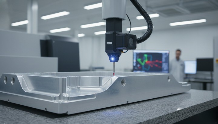
• Full GD&T measurement (CMM, optical, and height-gauge inspection)
• Engineering consultation for tolerance selection and fit behavior
• Material expertise for metals and close-tolerance plastics
• Statistical process control for high-volume projects
You benefit most when you treat the supplier as a technical partner, not just a machining vendor.
HM’s CNC Precision Capabilities for Tight Tolerance Functional Fits
You gain a measurable advantage when you work with a CNC manufacturer that understands how CNC machining tolerances, functional fits, and real-world assembly conditions interact. HM supports engineers who design mission-critical components, and we help you select tolerance values that protect performance while keeping cost under control. Our team combines precision CNC milling, CNC turning, and advanced inspection systems to deliver tight tolerance machining across metals and engineered plastics for industries that demand reliability.
We align our workflow with your drawings, tolerance stack-ups, ISO fit classes, and GD&T requirements. This lets you maintain consistent functional performance across prototypes, pre-production runs, and full-scale manufacturing.
CNC Milling, Turning, and Inspection Capabilities
Your parts benefit from HM’s vertically integrated machining capability. We operate multi-axis machining centers and high-rigidity turning equipment that maintain stable machining tolerances across complex or high-precision geometries. Our inspection systems verify GD&T requirements—including flatness, concentricity, position, and parallelism—so your assemblies behave predictably.
HM supports precision machining with:
• 3-axis, 4-axis, and 5-axis CNC milling centers
• High-rigidity CNC turning for shafts, bushings, and tight-fit components
• EDM for extremely tight tolerances and sharp internal features
• CMM inspection for GD&T controls and critical dimensions
• Optical and air-gage systems for micro-tolerance features
These capabilities allow us to support tolerance ranges from general machining levels to sub-0.01 mm requirements, depending on geometry and material.
You gain consistent quality when machining and inspection run under one roof, since data flows between departments and supports stable process control.
Supported Industries and Applications
HM delivers precision CNC machined parts for industries where tolerancing impacts performance, safety, or regulatory compliance. You gain a partner that understands your application—not just your drawing—so tolerances align with real functional needs.
Key industries we support include:
• Automotive: housings, connectors, brackets, powertrain components
• Aerospace: tight-fit assemblies, lightweight alloys, GD&T-controlled features
• Robotics: motion-critical shafts, bushings, and sensor mounts
• Medical: precision fixtures, surgical components, instrument housings
• Industrial machinery: sealing components, mechanical interfaces, alignment-critical parts
• Electronics: enclosures, heat-sink machining, precision aluminum parts
Each industry demands unique tolerancing standards, and we tailor our machining process to meet those requirements without unnecessary cost.
How HM Assists Engineers With Fit Selection and Manufacturability Optimization?
You reduce risk and improve functional reliability when HM’s engineering team helps you validate tolerances and choose the correct functional fit. We analyze how each dimension influences assembly behavior and identify areas where tolerances may be overly strict—or not strict enough.
Our engineering support includes:
• Reviewing your drawings to identify critical-to-function dimensions
• Mapping tolerance stack-up paths across assemblies
• Recommending ISO 286 fits for shafts, bearings, and sliding components
• Advising when GD&T controls (flatness, position, concentricity) improve stability
• Suggesting tolerance relaxations to reduce machining cost
• Providing alternative machining methods (e.g., EDM for ultra-tight features)
You gain confidence when your tolerances match both functional needs and production capability. This reduces design revisions, inspection failures, and unexpected cost increases.
FAQs About CNC Machining Tolerances
Engineers often need quick, practical answers when selecting CNC machining tolerances for new designs. These FAQs summarize the most common concerns and help you avoid costly mistakes.
What Is the Standard Tolerance for CNC Machining?
You typically use ±0.10 mm to ±0.05 mm for general CNC machining. Many suppliers treat ±0.10 mm as a default tolerance unless the drawing specifies otherwise. When parts require higher precision, you may tighten the tolerance to ±0.02 mm or ±0.01 mm depending on geometry, material, and CNC machine capability.
Standard ranges many engineers rely on:
• ±0.10 mm: general machining
• ±0.05 mm: standard precision
• ±0.01 mm: tight tolerance machining
• Below ±0.005 mm: EDM or high-precision workflows
Although these values reflect common global standards, you must always confirm the exact range with your manufacturer.
What Is Considered a Tight Tolerance?
A tight tolerance typically refers to ±0.02 mm or tighter, depending on feature type and material. For shafts, bearing seats, alignment interfaces, or GD&T-controlled surfaces, tight tolerances ensure precise assembly behavior. When tolerances fall below ±0.01 mm, machining often requires slower feeds, temperature control, more tooling changes, and advanced inspection.
Tight tolerances are most common in:
• Aerospace mechanisms
• Robotic joints or linear motion parts
• Medical devices with regulated performance
• Automotive transmission and powertrain components
You should only specify tight tolerances when functional needs demand it.
What Functional Fit Should I Choose?
Your fit selection depends on how the components interact. Clearance fits support free motion, transition fits support light press interactions, and interference fits create strong, non-moving joints.
General selection guidance:
• Clearance fit → sliding shafts, adjustable brackets
• Transition fit → accurate location with occasional adjustability
• Interference fit → press-fit bushings, gears, pulleys, bearing seats
You match these fits to ISO 286 shaft-hole combinations (H7/g6, H7/f7, H7/p6, etc.) to achieve predictable assembly results.
How Do I Reduce Cost While Meeting Functional Fit Requirements?
You reduce cost by matching tolerances to functional needs instead of applying blanket tight values. You can relax non-critical features while keeping strict tolerances only where alignment, motion, or sealing depend on precision.
Practical strategies include:
• Relaxing tolerances on aesthetics and non-contact surfaces
• Simplifying GD&T controls to reduce measurement time
• Avoiding sub-0.01 mm tolerances unless absolutely required
• Considering alternate manufacturing processes for ultra-tight features
• Discussing cost impacts during early DFM review with your supplier
This approach protects functionality while controlling CNC manufacturing cost.
Conclusion

You gain better product reliability and lower machining costs when you understand how CNC machining tolerances, functional fits, and GD&T interact. Good tolerance planning helps you balance performance with manufacturability, avoid unnecessary tight tolerances, and achieve consistent assembly behavior. When tolerances reflect real functional needs, your components operate more smoothly and maintain long-term stability.
A structured approach to tolerancing—supported by DFM review, material understanding, and collaboration with your CNC supplier—helps you design parts that meet engineering goals without creating avoidable expense or production delays. If you want expert guidance or need help validating tolerances on your drawings, send your CAD files to HM for a professional tolerance review