


When you source CNC machining, quality control workflow matters more than any single quote or spec sheet.
Many buyers pay the price for unclear processes: good-looking samples, but unstable series production; nice presentations, but no real traceability when something goes wrong. In sectors like automotive, robotics, and medical, a single out-of-tolerance part can stop a line, trigger field failures, or damage your brand. You do not just need precision parts; you need a supplier with a controlled, repeatable way to deliver them.
In this article, you will see how a structured CNC machining quality control process works from RFQ to shipment, what checks happen at each stage, and how this protects your projects, budgets, and timelines when you work with an external machining partner.
What CNC Buyers Need from a CNC Machining Quality Control Process?
CNC buyers need a quality control workflow that consistently delivers parts that match drawings, function in assembly, and arrive on time with clear documentation.
Beyond a simple “final inspection,” an effective workflow should help you avoid late surprises, reduce rework at your plant, and give you confidence that the supplier can support future ramp-up or design changes. It should be visible, documented, and aligned with your own internal quality requirements, not a black box on the supplier’s side.
To reach that level, you need more than a skilled machinist. You need process control plus traceable documentation. Process control keeps machining stable. Documentation shows what happened and proves that parts meet requirements.
Typical risks you want to control include:
-
Parts within nominal dimensions but failing GD&T in assembly.
-
Variation between batches because of tool wear or different operators.
-
Missing material certificates or incomplete inspection reports during audits.
-
Delays caused by late discovery of nonconforming parts at your incoming inspection.
A transparent CNC machining quality control process addresses these risks step by step, long before parts reach your line.
Overview of Our End-to-End CNC Quality-Controlled Manufacturing
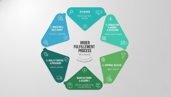
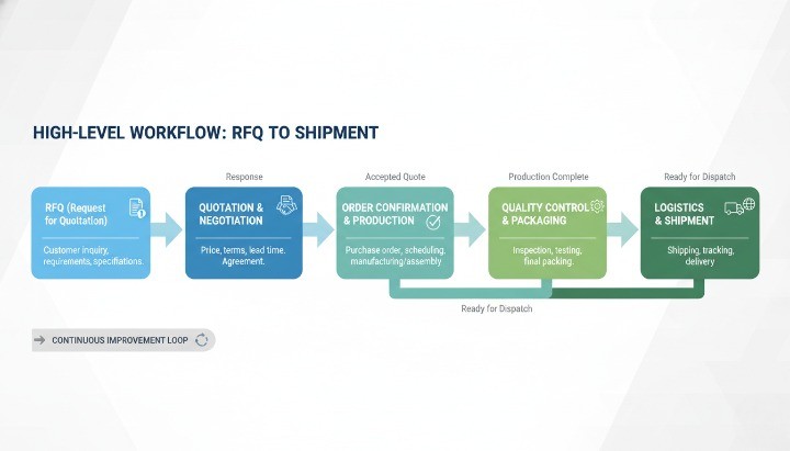
Our CNC machining quality control process follows your part from drawing to delivery in six core stages.
We start with RFQ and design for manufacturability (DFM), move through material and tooling checks, prove out the process with first article inspection (FAI), stabilize it with in-process control, and finish with final inspection, documentation, and shipment release. At every stage, we capture data and decisions so you can trace how quality is built into each batch of parts.
Six core stages in our CNC machining quality control process:
-
RFQ, DFM review, and control plan definition.
-
Incoming quality for material, tooling, and machines.
-
CNC programming, trial runs, and FAI.
-
In-process control on the shop floor.
-
Final inspection, assembly, and functional validation.
-
Documentation, traceability, and shipment release.
We integrate these steps within a quality management framework based on ISO 9001 principles, which focus on consistent processes, risk-based thinking, and continuous improvement.
If you already work under internal systems such as IATF-style controls or supplier quality manuals, we can map our workflow to your internal quality and compliance requirements so your audits and PPAP-style reviews move faster.
Quality Control vs Quality Assurance in CNC Machining
Quality control (QC) and quality assurance (QA) are often used interchangeably, but they serve different roles in CNC machining.
Quality control focuses on inspection and verification. It includes CMM measurement, hardness testing, surface finish inspection, and dimensional validation to ensure parts meet drawing requirements.
Quality assurance focuses on the system behind the process. It includes ISO 9001-based procedures, training, documentation control, corrective actions (CAPA), and continuous improvement programs.
An effective CNC machining quality system combines both QC and QA.Inspection alone cannot guarantee consistency; a structured quality management system ensures repeatability across batches and long-term programs.
Stage 1 – RFQ, DFM Review, and Control Plan for CNC Machining
A robust CNC machining quality control process starts at the RFQ stage, not at the inspection table.
When we receive your 2D drawings, 3D models, and specifications, we review them with engineering, manufacturing, and quality together. The goal is to understand not only what the part looks like but also how it functions in your assembly and how sensitive it is to variation.
We look at:
-
Dimensional tolerances and GD&T callouts.
-
Surface finish and cosmetic requirements.
-
Material grade and any heat treatment.
-
Special features such as threads, thin walls, or tight position tolerances.
Based on this review, we provide DFM recommendations when needed. For example, we may suggest slightly larger radii, adjusted tolerance zones, or alternative chamfer details that maintain function but improve machinability and stability. These discussions help prevent quality issues later, such as chatter marks, warping, or impossible datums.
Once we agree on the approach, we build a control plan for CNC machining. This plan defines:
-
Critical and significant characteristics to monitor.
-
Measurement methods and inspection tools.
-
Sampling frequency during production.
-
Required documentation (FAI, dimensional reports, certificates).
By aligning acceptance criteria and quality levels with you at this early stage, we avoid vague expectations and reduce the risk of disputes after parts arrive.
For more complex projects or ongoing programs, this planning also connects with our broader .

Stage 2 – Incoming Quality: Material, Tooling, and Machine Readiness
Before we cut any metal, we verify that material, tooling, and machines are ready to produce conforming parts.
We start with raw material verification. We check material certificates (such as EN 10204 3.1) and cross-check grade, heat number, and mechanical properties against your drawing and standards. This step ensures that the base material for aluminum, steel, or other alloys truly matches your requirements, which is essential for fatigue strength, corrosion performance, and downstream treatments.
We also inspect tooling and fixtures. A stable, repeatable setup is a major factor in holding tight tolerances. We confirm clamping, support surfaces, and reference datums so that parts sit consistently for each operation, especially in multi-axis setups.
Next, we check our measuring instruments. Calipers, micrometers, height gauges, and coordinate measuring machines (CMMs) follow a calibration schedule aligned with recognized metrology practices. A stable measurement system is critical; without it, even a good process cannot prove conformity with confidence.(Source:)
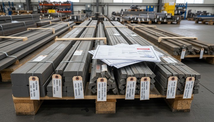
We also set up traceability at this stage. Material batches, tool setups, and job travelers receive internal IDs so we can link the finished parts back to material certificates, inspection records, and machine setups. If an issue ever occurs, this traceability allows us to isolate affected parts quickly instead of stopping entire product families.
Stage 3 – CNC Programming, Trial Runs, and First Article Inspection (FAI)
In Stage 3, we translate your design into a stable CNC machining process through programming, trials, and first article inspection.
Our programmers create toolpaths in CAM with a focus on maintaining tolerances, controlling surface finish, and keeping cycle times efficient. We choose tools, cutting parameters, and strategies that balance speed with stability. For features such as tight bores, precision slots, or complex profiles, we prioritize repeatability and dimensional control over aggressive feeds and speeds.
We then run a trial batch or first-off parts. Operators and engineers check the machine setup, verify zero points and offsets, and watch for signs of vibration, deflection, or thermal drift. This is where we adjust tool lengths, speeds, and feeds to achieve the desired results.
The key deliverable in this stage is the First Article Inspection (FAI) report. For the FAI, quality inspectors measure all or a defined set of dimensions, including critical characteristics and GD&T features, using calibrated tools and CMM where needed. We document results, deviations (if any), and process notes.
For customers in automotive or similarly demanding sectors, we can also support PPAP-style documentation packages, which may include:
-
Process flow diagrams.
-
Detailed control plans.
-
Capability studies on key dimensions.
-
FMEA-based risk assessments if requested.
Only when the FAI meets agreed criteria do we release the CNC machining process for ongoing production. This approach avoids discovering fundamental issues in the middle of a large batch.
If you want to learn more about how we handle complex metal parts, you can also see our guide to . (Source:)

Stage 4 – In-Process Control: Machine Shop Quality Control Procedures
Once production starts, in-process control keeps the machining process stable and predictable.
We do not rely on final inspection alone. Instead, we embed checks into the machining process itself. Operators and quality staff follow clear machine shop quality control procedures that define what to measure, how often to measure it, and what to do when results drift toward specification limits.
A typical in-process control setup includes:
-
Operator self-inspection on defined dimensions at set piece counts.
-
Dedicated QC checkpoints for critical dimensions or complex GD&T.
-
Verification of tool wear, offset adjustments, and surface finish.
-
Spot checks on positioning, concentricity, and perpendicularity as needed.
For stable, higher-volume production, we may apply statistical process control (SPC). SPC uses statistical methods and control charts to monitor process behavior in real time, detect trends, and trigger corrective actions before parts go out of tolerance.(Source:)
The goal is simple: catch variation early, when it is still cheap to correct. Adjusting a tool offset or replacing an insert during the run is far less costly than scrapping a finished lot or rejecting parts at your incoming inspection.
We also monitor external factors that affect accuracy, such as machine temperature, coolant condition, and chip evacuation. These may sound like small details, but over a long production run they can shift dimensions enough to cause assembly problems.

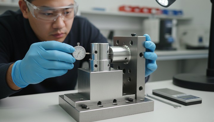
CMM Inspection in CNC Machining Quality Control
Coordinate Measuring Machine (CMM) inspection is one of the most important tools in modern CNC machining quality control. Unlike traditional tools such as calipers or micrometers, a CMM measures complex geometries in three dimensions and verifies tight GD&T requirements with very high accuracy, typically within ±0.002 mm depending on machine class.
CMM inspection is especially critical for aerospace, automotive, robotics, and medical components where positional tolerance, concentricity, flatness, and alignment directly affect assembly performance. A structured CMM inspection process allows us to generate detailed dimensional reports, validate geometric tolerances, and provide documented evidence of compliance.
By integrating CMM inspection into our ISO 9001 quality management workflow, we ensure that complex features are verified using repeatable, calibrated measurement systems rather than visual judgment or limited manual tools.
Hardness Testing Methods for CNC Machined Parts
Hardness testing verifies whether a machined component meets its required mechanical performance after machining or heat treatment. Dimensional accuracy alone is not enough; material strength and resistance to deformation must also be confirmed.
Common hardness testing methods include:
Rockwell hardness testing – widely used for steel and hardened alloys
Brinell hardness testing – often used for cast materials and softer alloys
Vickers hardness testing – suitable for thin sections or high-precision components
Including hardness testing within the CNC machining quality control process ensures that components meet both dimensional and material performance requirements. This is particularly important for parts exposed to load, wear, or fatigue in automotive and industrial applications.
Surface Roughness Inspection and Ra Standards
Surface roughness directly influences sealing performance, wear resistance, and assembly behavior. In CNC machining, surface finish is typically specified using Ra values, measured in micrometers or microinches.
Surface roughness inspection is conducted using a profilometer to measure Ra values across critical surfaces. Typical requirements include:
Ra 0.4–0.8 μm for sealing faces and precision sliding components
Ra 1.6–3.2 μm for general mechanical surfaces
Ra 6.3 μm for non-critical structural parts
By combining surface roughness inspection with dimensional checks and GD&T verification, we ensure that parts not only meet drawing dimensions but also perform reliably in real-world operating conditions.
Stage 5 – Final Inspection, Assembly, and Functional Validation
In Stage 5, we confirm that finished CNC machined parts and assemblies meet all drawing and functional requirements before shipment.
Depending on your project and risk level, we define an inspection strategy that combines sampling and, where required, 100% checks on specific features. High-risk features that directly affect safety, sealing, or alignment may receive special attention.
Final inspection typically includes:
-
Dimensional verification with CMM, height gauges, and dedicated gauges.
-
Geometric tolerance checks for position, flatness, runout, and perpendicularity.
-
Surface finish checks against Ra requirements and cosmetic standards.
-
Visual inspection for burrs, sharp edges, scratches, and contamination.
When assemblies or mating parts are involved, we perform assembly and fit verification. We test how parts seat, rotate, or seal under realistic conditions. This step often reveals issues that pure dimensional checks cannot catch, such as stack-up effects or interference under torque.
To make this clearer, the table below summarizes typical inspection strategies:
| Inspection Aspect | Typical Approach | When Used |
|---|---|---|
| Dimensional checks | Sampling + critical 100% | Most CNC machined parts |
| GD&T on critical features | CMM or dedicated gauges | Tight tolerance, alignment, or sealing surfaces |
| Surface finish | Profilometer + visual standards | Cosmetic parts, sealing faces, sliding surfaces |
| Assembly / fit tests | Functional fixtures or trial assembly | Machined mechanical assemblies and mating parts |
In advanced production programs, final inspection data is often supported by CMM reports, statistical process control (SPC) summaries, and surface finish measurement records. These reports allow customers to confirm compliance before shipment and reduce incoming inspection workload. A documented inspection package not only proves conformity but also strengthens long-term supplier qualification.
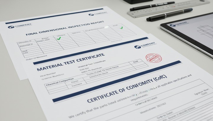
Stage 6 – Documentation Package, Traceability, and Shipment Release
Before we release any shipment, we assemble the documentation and verification that prove conformity.
A standard quality documentation package for CNC machined parts may include:
-
Dimensional inspection report (including FAI when applicable).
-
Certificate of conformity (COC) confirming compliance with drawing and PO.
-
Material certificate (e.g., EN 10204 3.1) from the mill or supplier.
-
Certificate of origin (CO) when required for customs or trade agreements.
For projects that need deeper validation, we can provide advanced quality control options such as:
-
3D optical scanning to compare parts to CAD models.
-
CT scanning for internal features on complex components.
-
Detailed surface roughness measurement reports on critical surfaces.
All documentation links back to traceability records: batch IDs, heat numbers, job travelers, and machine setups. We maintain records according to our quality management procedures and, where requested, your specific retention requirements.
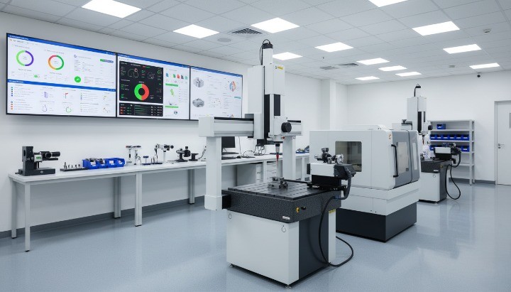
Quality Standards, Inspection Equipment, and Digital QMS Behind Our Workflow
Our quality management system follows the principles of ISO 9001, the globally recognized framework for process control, risk-based thinking, documentation, and continuous improvement. In CNC machining, ISO 9001 supports structured control plans, calibrated inspection equipment, corrective action systems (CAPA), traceable documentation, and consistent verification from RFQ to shipment.(Source:)
By aligning our CNC machining quality control process with ISO 9001 standards, we reduce variability, improve process stability, and ensure that inspection results are repeatable and auditable. This structure allows engineering teams to validate performance and procurement teams to control supplier risk effectively.
Our CNC Inspection Capabilities
To support precision manufacturing, our inspection capability includes:
• CMM measurement accuracy up to ±0.002 mm
• Minimum dimensional tolerance capability: ±0.005 mm (depending on geometry)
• Surface finish capability down to Ra 0.4 μm
• Hardness testing after heat treatment verification
• 100% traceable batch and material control system
• Digital inspection reports for dimensional and GD&T verification
These capabilities allow us to maintain stable quality across prototype and mass production projects.
If you want to see how this connects to real products, you can review our and .
Tailored Control Plans for Different Industries and Risk Levels
Different industries and projects do not need the same depth of CNC machining quality control, so we tailor control plans to match risk and cost.
For prototypes and early development, you may prioritize speed and feedback over extensive documentation. For mass production in automotive or medical applications, you may require detailed reports, capability studies, and structured change control. The right balance keeps you safe without overpaying for unneeded checks.
We typically adapt control depth along three axes:
-
Project phase: prototype, pilot run, or stable series production.
-
Industry and regulatory environment.
-
Part function and risk if failure occurs.
-
Prototypes: lighter sampling, focus on learning and DFM feedback.
-
Small batches for industrial machinery: targeted checks on critical dimensions and fits.
-
High-volume automotive or safety-related parts: comprehensive control plans, SPC, and PPAP-style documentation.
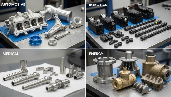
Our experience with CNC machined parts for automotive, robotics, medical, and energy applications helps us understand how different sectors view risk and compliance. In each case, our CNC machining quality control workflow stays the same in structure, but we adjust the intensity and documentation level to match your internal audit and supplier management systems.
We also customize reporting formats and data fields so your quality teams can integrate our information into their own databases or PLM/ERP systems without manual rework. This reduces friction and makes it easier to add us as a long-term approved supplier.
How Our CNC Quality Control Process Supports Engineering and Procurement
A structured CNC machining quality control process supports both engineering and procurement teams in different but connected ways.
For engineering, the workflow reduces design risk. Early DFM reviews, clear control plans, and FAI reports help you confirm that the design can be manufactured reliably. Changes happen sooner, while they are still cheap, instead of during ramp-up or after field feedback.
For procurement, the workflow stabilizes total cost and delivery performance. Stable processes and traceable inspection reduce unexpected scrap, returns, and line stops. Consistent documentation simplifies supplier audits and qualification. Over time, this can lower the total cost of poor quality and strengthen your negotiation position because you understand exactly what level of control you are buying.
From our side, transparent communication is crucial. We share sample reports, discuss control plans, and agree on checkpoints before full production. If an issue arises, we show how we will contain it, correct it, and prevent recurrence. This approach treats quality control as a shared risk management tool, not just paperwork.
When you evaluate any CNC supplier’s quality control workflow, you can start with questions like:
-
How do you build the control plan for CNC machining parts?
-
Which dimensions do you monitor in-process, and how often?
-
What inspection equipment and software do you use?
-
What documentation do you provide by default, and what can be added?
Suppliers who can answer these questions clearly and show evidence of their methods usually offer lower long-term risk, even if their unit price is not the lowest on the spreadsheet.
FAQs
What is a CNC machining inspection process?
A CNC machining inspection process includes dimensional measurement, GD&T verification, surface roughness inspection, hardness testing, and documentation review. Measurement tools such as CMM systems, micrometers, and profilometers are used to ensure parts conform to drawing specifications.
What is First Article Inspection (FAI)?
First Article Inspection (FAI) verifies the first produced part from a new setup against all dimensional and geometric requirements. A complete FAI report confirms that the machining process is stable before full production begins.
How does ISO 9001 improve CNC machining quality?
ISO 9001 provides a structured framework for process control, documentation, corrective action, and continuous improvement. In CNC machining, it ensures traceability, standardized inspection procedures, and controlled change management.
Why is surface roughness inspection important?
Surface roughness affects sealing, friction, wear resistance, and aesthetic appearance. Measuring Ra values ensures that machined surfaces meet functional and performance requirements.
What inspection equipment is used in CNC machining?
Typical inspection equipment includes coordinate measuring machines (CMM), hardness testers, profilometers, height gauges, micrometers, and digital quality control systems for traceability and reporting.
Start Your Next CNC Machining Project With a Proven Quality Control Workflow
If you want more than a price quote, you need a CNC machining partner with a proven, transparent quality control workflow from drawing to delivery.
When you share your drawings, 3D models, and quality requirements with us, we review them with manufacturing and quality together. We propose a control plan, agree on documentation, and support you through prototypes, pilot runs, and stable production. You can also explore our and pages to see the range of components we handle.
If you would like to see how this looks in practice, you can request a sample inspection report or example control plan based on a real part. Once you are ready, send your RFQ and quality requirements, and we will respond with a CNC machining quality control workflow and quotation built around your risk, documentation, and cost targets
Pingback: hello world