


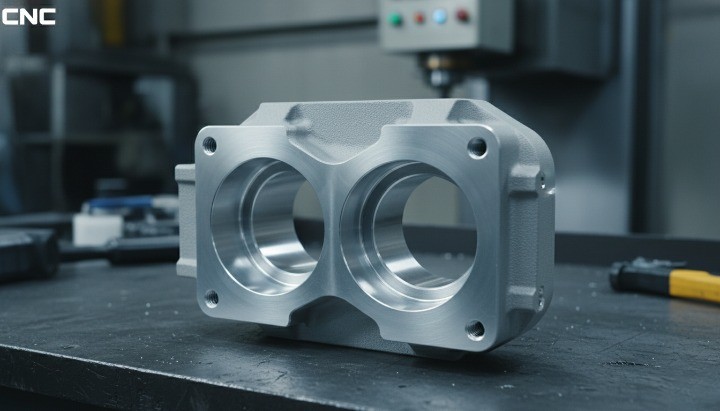
CNC machining and die casting services from HM support robotics component development by turning precise designs into reliable robot hardware.
Many teams struggle to connect elegant CAD models with real-world parts that align, move smoothly, and survive daily operation. Misjudged tolerances, material choices, or suppliers can lead to backlash, vibration, unexpected failures, and costly redesigns that slow down projects and damage trust with end customers.
This guide gives you a practical framework to design, specify, and source CNC machined robot parts with confidence, so you reduce risk, control cost, and build robotics systems that perform consistently in the field.
Overview of CNC machined robotics components
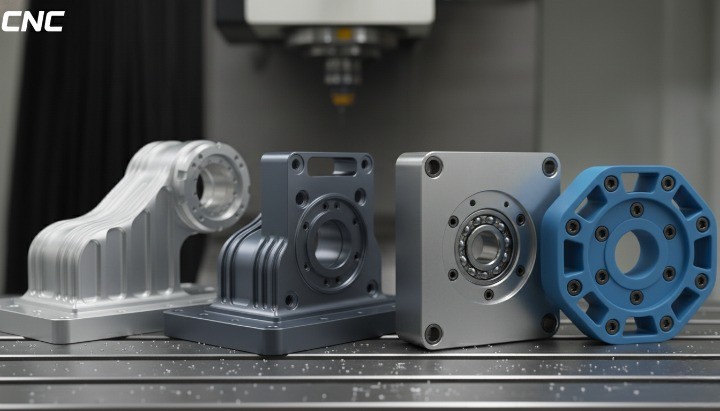
Robotics systems depend on a large family of CNC machined components that work together as a mechanical backbone. These parts turn abstract kinematics and control algorithms into real, physical motion that must stay accurate over thousands or millions of cycles.
Typical CNC machined robotics components include structural bases and arms, joint housings and bearing blocks, precision mounting plates, end-of-arm tooling bodies, custom gripper fingers, motor and gearbox brackets, and sensor or camera mounts. Many teams also use CNC machining for robot-specific fixtures, calibration tools, and alignment jigs that support assembly and maintenance.
What ties these parts together is the combination of tight tolerances, repeatable geometry, and application-specific materials. In most cases, they cannot rely on off-the-shelf hardware alone. The integration of these machined components defines how well your robot holds position, resists deflection, handles shock loads, and maintains accuracy as it ages.
As you move from prototypes to production robots, CNC machining remains crucial. It allows you to refine geometries, localize stiffness, integrate more functions into single parts, and support consistent quality across different batches, factories, or customer variants.
Why CNC Machining Is Essential for Robotics Components?
CNC machining is essential for robotics components because robots rely on mechanical precision to deliver predictable motion, positioning accuracy, and long-term stability. Unlike general industrial equipment, robots amplify even small geometric errors through their kinematic chains. A few microns of misalignment in one joint can translate into millimeters of error at the end effector.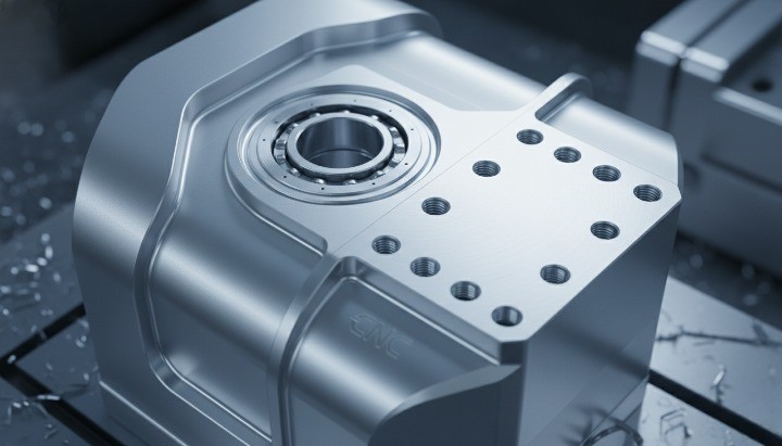
Beyond precision, CNC machining also supports rapid iteration. Robotics development rarely follows a straight path from design to mass production. Engineers adjust arm lengths, joint stiffness, motor interfaces, and tooling layouts as systems are tested. CNC machining allows these changes to translate quickly into physical parts without long tooling delays.
Together, precision, repeatability, and flexibility explain why CNC machining sits at the core of modern robotics manufacturing, from early prototypes to mature production platforms.
Precision, repeatability, and motion accuracy requirements
Robotic motion accuracy starts with mechanical accuracy. Control software and sensors can only compensate for so much. If the physical components drift, flex, or misalign, no amount of tuning can fully recover performance.
-
Bearing bores that maintain concentricity and preload over time
-
Flat and parallel mounting faces that define joint reference planes
-
Dowel and locating features that ensure repeatable assembly
-
Shaft interfaces that minimize runout and backlash
These features directly influence repeatability, which many robotics standards measure as the robot’s ability to return to the same position repeatedly, not just reach a target once. According to ISO 9283, repeatability is one of the defining performance metrics for industrial robots, and mechanical fit plays a decisive role in achieving it.
CNC machining also supports stable performance under dynamic conditions. Robots accelerate, decelerate, and change direction continuously. Poorly controlled wall thickness, uneven material removal, or inconsistent tolerances create stress concentrations and micro-movements. Over time, these issues lead to vibration, noise, and wear that degrade accuracy long before electronic components fail.
By producing parts with consistent geometry and predictable surface finishes, CNC machining helps designers maintain stiffness and alignment throughout the robot’s service life. This stability reduces re-calibration needs and lowers total ownership cost for end users.
CNC machining vs alternative manufacturing processes in robotics
Robotics teams often evaluate multiple manufacturing processes before committing to CNC machining. Each process has its place, but their limitations become clear when performance requirements increase.
The table below summarizes how CNC machining compares with common alternatives used in robotics development and production.
| Manufacturing Process | Strengths in Robotics | Key Limitations |
|---|---|---|
| CNC Machining | High precision, repeatability, broad material choice, strong mechanical properties | Higher unit cost at very high volumes |
| 3D Printing | Fast iteration, complex internal geometry | Lower strength, poorer tolerance control |
| Sheet Metal Fabrication | Low cost for simple enclosures and brackets | Limited stiffness, poor precision at joints |
| Die Casting | Low cost at high volume, complex shapes | High tooling cost, post-machining still required |
| Injection Molding | Excellent surface finish, high-volume efficiency | Not suitable for load-bearing metal parts |
 3D printing is valuable during early concept stages, especially for form checks or simple fixtures. However, printed polymer parts lack the stiffness and dimensional stability required for most structural or motion-critical robot components. Metal additive manufacturing improves strength but still struggles with cost, surface finish, and tolerance consistency for precision interfaces.
Sheet metal works well for guards, covers, and enclosures. Yet it cannot reliably deliver the flatness, perpendicularity, or bearing fits needed in joints, drive systems, or precision mounts. Robotics designers often combine sheet metal with CNC machined brackets or inserts to compensate for these limitations.
Die casting becomes attractive when robotics platforms mature and volumes increase. Even then, critical features almost always require CNC finishing. Bearing seats, datum faces, threads, and sealing surfaces must be machined after casting to meet functional requirements.
For these reasons, CNC machining remains the reference process for robotics components where accuracy, reliability, and mechanical integrity directly affect system performance. Other methods may support it, but they rarely replace it in precision-critical applications.
Robotics Components Most Suitable for CNC Machining
CNC machining best serves robotics components that directly influence accuracy, stiffness, repeatability, and system reliability, especially for custom CNC mechanical components used in load-bearing and alignment-critical robot structures. These parts usually carry loads, define alignment, or transmit motion. As a result, they demand tight tolerances, controlled geometry, and consistent material properties that CNC machining delivers reliably across prototypes and production runs.
From robot bases to end-of-arm tooling, CNC machining allows engineers to fine-tune mechanical performance while keeping designs manufacturable. The sections below break down the main robotics component groups where CNC machining adds the most value and why alternative processes often fall short.
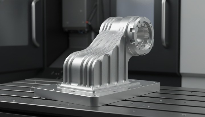
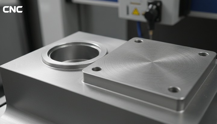
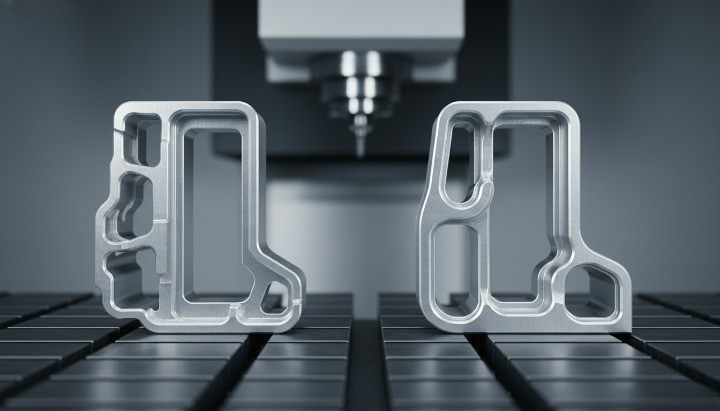
Structural robot components (bases, frames, arms, mounting plates)
Structural components form the mechanical backbone of any robot. They define stiffness, mass distribution, and how loads travel through the system during acceleration, deceleration, and repetitive motion. CNC machining is the preferred process for these parts because geometry control directly affects precision and vibration behavior.
Common CNC machined structural elements include robot bases, arm segments, cross members, and interface plates connecting joints or external equipment. These parts often require flatness, parallelism, and perpendicularity to stay within tight limits. Small deviations at this level become magnified at the robot’s reach, especially in long-arm or high-speed applications.
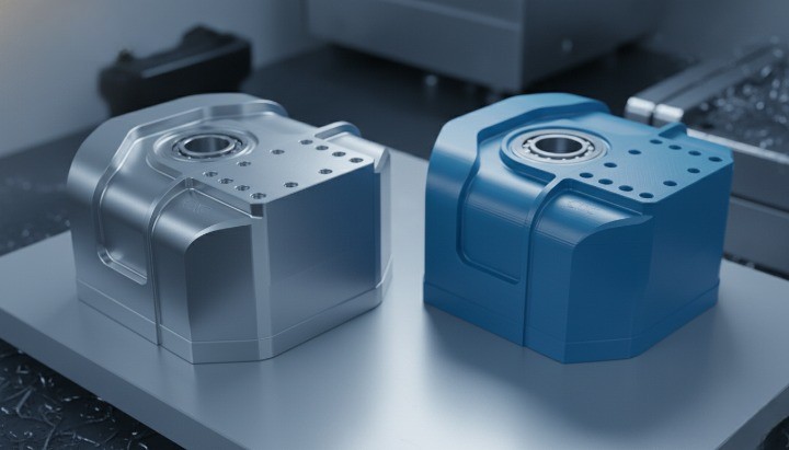
Aluminum alloys are widely used for robot structures due to their strength-to-weight ratio and machinability. CNC machining allows engineers to integrate ribs, pockets, and mounting features directly into a single part, reducing assembly stack-up and improving stiffness without unnecessary mass. Steel structures, when required, also benefit from CNC machining to maintain accurate interfaces after welding or heat treatment.
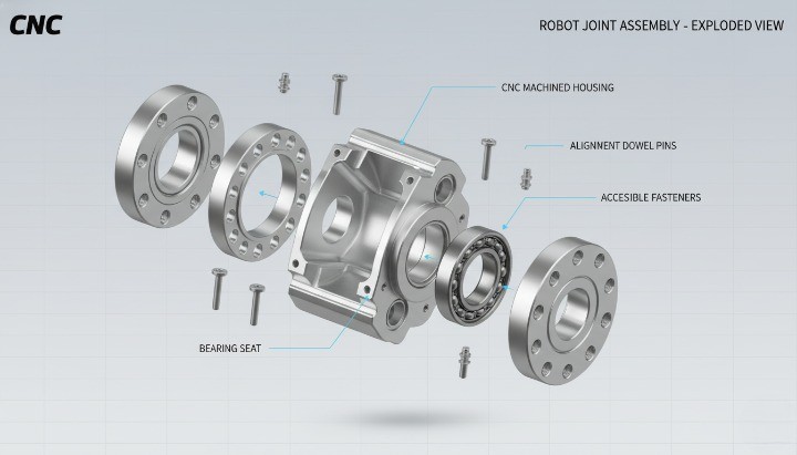
Joint and motion-related components (housings, bearing seats, couplings)
Joint components sit at the heart of robotic motion. They house bearings, gears, shafts, and drive elements that determine backlash, repeatability, and service life. CNC machining is essential here because joint performance depends on microns, not millimeters.
Bearing seats, for example, require controlled diameters, roundness, and surface finish to achieve proper preload and longevity. Poorly machined housings can lead to uneven load distribution, early bearing failure, and loss of positional accuracy. CNC machining provides the control needed to maintain these critical interfaces across batches.
Couplings, flanges, and joint adapters also rely on concentricity and accurate bore-to-face relationships. CNC processes allow these features to be machined in a single setup, reducing cumulative error. This consistency directly impacts calibration effort and long-term maintenance for the end user.
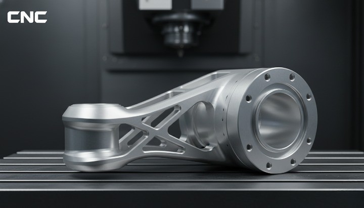
End-of-arm tooling (EOAT) and end effectors
End-of-arm tooling is one of the most customized areas of robotics, and CNC machining plays a central role. Grippers, tool adapters, vacuum manifolds, and custom billet aluminum parts such as end-effector bodies and adapters must balance precision, lightweight design, and durability.
CNC machining allows engineers to tailor EOAT geometry to specific tasks. Pocketing removes excess material to reduce inertia, while threaded ports, precision mounting faces, and sensor features integrate multiple functions into one component. This level of integration is difficult to achieve consistently with fabrication or additive methods.
Repeatable mounting is another key factor. EOAT often changes frequently, either for product variants or maintenance. CNC machined interfaces with dowel pins or precision slots ensure that tools return to the same position without recalibration, reducing downtime on production lines.

Drive and transmission-related components
Robotic drive systems convert motor torque into controlled motion. CNC machined components such as motor mounts, gearbox housings, pulley hubs, and shaft adapters play a decisive role in this process. Their geometry affects alignment, efficiency, and noise.
Accurate positioning of motors and gearboxes prevents uneven loading and premature wear. CNC machining ensures that bolt patterns, pilot diameters, and mounting faces align correctly, even when tolerances are tight. For belt or chain systems, concentricity and balance are essential to minimize vibration at high speed.
In many robots, these components also interface with structural parts. CNC machining allows designers to manage these interfaces precisely, reducing the need for shims or manual adjustment during assembly.
Sensor, vision, and electronics mounting parts
Sensors and cameras extend a robot’s capabilities, but only if they stay accurately positioned. CNC machined mounting parts provide the stability required for vision systems, force sensors, encoders, and protective enclosures.
These components often include fine adjustment slots, reference surfaces, and protective geometries. CNC machining maintains the repeatability of these features so calibration remains valid even after maintenance. It also allows designers to add shielding or integrated cable routing without compromising accuracy.
Although these parts may appear secondary, their impact is significant. Poorly aligned sensors lead to faulty feedback, reduced accuracy, and unreliable operation. CNC machining helps ensure that sensing hardware performs as intended throughout the robot’s life cycle.
Material Selection for CNC Machined Robotics Components
Material choice directly shapes the performance, cost, and service life of robotic systems. Even with perfect geometry, the wrong material leads to deflection, wear, corrosion, or unnecessary weight. CNC machining parts give engineers the freedom to work with a wide range of metals and plastics, but successful robotics design still depends on matching material properties to real operating conditions.
In this section, we focus on the materials most commonly used for CNC machined robotics components and explain why each one fits specific robotic functions. The goal is not to list every option, but to help you make practical, defensible decisions during design and sourcing.
Aluminum alloys for lightweight robot structures
Aluminum alloys are the most widely used materials for CNC machined robotics components, especially where low mass and structural stiffness must coexist. Reducing weight lowers inertia, improves acceleration, and decreases energy consumption, which matters for both industrial robots and mobile platforms.
Alloys such as 6061 and 6082 are common choices for robot bases, arms, mounting plates, and brackets. They offer a balanced combination of strength, machinability, and availability. For higher stiffness and load capacity, many designers turn to 7075, particularly for joint interfaces or long arm sections where deflection directly affects accuracy.
CNC machining allows aluminum structures to be optimized through pocketing and ribbing. Instead of relying on uniform thickness, engineers can place material only where loads travel. This approach improves stiffness-to-weight ratio without adding assembly complexity. Anodizing or conversion coatings further enhance corrosion resistance and surface durability, making aluminum suitable for many factory environments.
Steel and stainless steel for high-load and harsh environments
Steel becomes the preferred choice when robotic components face high loads, shock forces, or demanding environmental conditions. Compared with aluminum, steel provides higher modulus of elasticity, which translates to reduced deflection under the same load. This makes it suitable for heavy-duty joints, load-bearing frames, and drive system interfaces.
Carbon steels are often used in structural parts where weight is less critical and maximum stiffness is required. After welding or heat treatment, CNC machining brings interfaces back into tolerance, ensuring accurate assembly. Tool steels may appear in wear-critical components such as cams or guides, where surface hardness extends service life.
Stainless steel serves a different purpose. Grades like 304 and 316 are widely used in robotics applications exposed to moisture, chemicals, or washdown procedures, including food processing, medical automation, and laboratory systems. CNC machining delivers precise sealing surfaces, threads, and mounting features while preserving corrosion resistance.
Although steel parts cost more to machine due to longer cycle times and tool wear, they often reduce risk and maintenance cost in demanding applications. In many robotic designs, engineers combine steel at critical load paths with aluminum elsewhere to balance performance and weight.
Engineering plastics for functional robotics components
Engineering plastics play an important supporting role in CNC machined robotics components, especially where low friction, electrical insulation, or chemical resistance matters more than structural stiffness. CNC machining works well for plastics because it produces clean edges, accurate dimensions, and consistent geometry without expensive tooling.
Materials such as POM (acetal) are often used for wear strips, guides, spacers, and low-load sliding elements. Their low friction and good dimensional stability reduce the need for lubrication. Nylon (PA) appears in covers, brackets, and components that benefit from impact resistance and vibration damping.
For higher-end applications, PEEK and similar high-performance plastics handle elevated temperatures and aggressive chemicals. These materials are common in medical, cleanroom, and specialized industrial robots. CNC machining allows tight tolerance control, which is essential because plastic parts often mate directly with metal components.
Despite their advantages, plastics require careful design. Wall thickness, creep behavior, and thermal expansion differ significantly from metals. CNC machining helps manage these challenges by holding tolerances accurately, but material selection must still account for long-term load and environmental exposure.
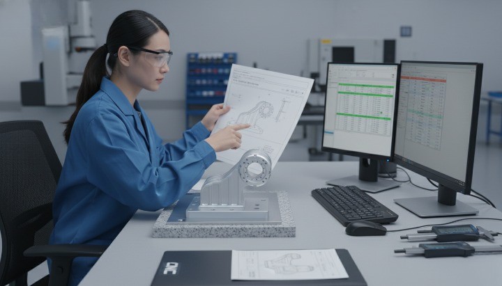
Tolerance, GD&T, and Surface Finish Requirements in Robotics
Robotic systems only achieve their specified accuracy and repeatability when tolerances, GD&T, and surface finish are treated as design-level decisions, not afterthoughts. Control software and sensors can improve performance, but they cannot fully compensate for loose bearing fits, warped mounting faces, or rough sliding contacts. For CNC machining for robotics components, these three elements connect the drawing to real-world motion.
Well-chosen tolerances protect the robot’s pose repeatability and stability. ISO 9283, which defines test methods for robot pose accuracy and repeatability, takes a mechanical baseline for granted: the structure and joints must already meet their intended fit and stiffness levels. GD&T then becomes the shared language between design, machining, and inspection. Surface finish completes the picture by governing friction, sealing, and fatigue behavior at contact interfaces.

Critical tolerances in robotic assemblies
Critical tolerances in robotic assemblies are the dimensions and relationships that most strongly influence pose accuracy, repeatability, stiffness, and wear. If you control only a subset of features, focus here first. These tolerances appear in joints, structural interfaces, and sensor mounting, where small errors quickly propagate through the robot’s kinematic chain.
Typical tolerance-critical features include:
-
Bearing bores and seats, where diameter, roundness, and coaxiality define preload and life
-
Datum faces on bases, arms, and gearboxes that set the orientation of each axis
-
Dowel holes, slots, and precision pins that ensure repeatable assembly and replacement
-
Shaft interfaces, such as keyways or clamping hubs, that control runout and backlash
Industrial robot pose repeatability, as characterized in ISO 9283, depends heavily on how these features behave under load and over time. A robot that looks accurate during a factory acceptance test can drift out of tolerance if bearing fits relax or joint housings distort under stress. Tight tolerances in the right places reduce this risk and make calibration more durable.
From a sourcing perspective, you do not need to tighten every dimension. You gain more by defining a small set of critical tolerances and letting other dimensions follow general machining standards. This approach keeps inspection focused and allows your CNC partner to optimize cycle time while still protecting system-level performance.
Applying GD&T to control robot motion accuracy
Geometric dimensioning and tolerancing (GD&T) gives you a structured way to describe how robotic parts must relate to each other in 3D space. Instead of relying only on linear plus/minus tolerances, you specify the allowable variation in form, orientation, and location relative to datums that reflect real assembly conditions. ISO’s Geometrical Product Specification (GPS) framework, and standards like ISO 1101, define this common language.
For robotics, GD&T is especially powerful when you want to control:
-
The position of hole patterns that connect arms, joints, and tool plates
-
The perpendicularity and parallelism of mounting faces that define joint axes
-
The concentricity or runout of shafts, pulleys, and couplings relative to bearings
-
The flatness of reference surfaces used for calibration or metrology fixtures
By tying these features to a coherent datum scheme, you make it easier for CNC machinists and inspectors to understand what truly matters. This reduces interpretation errors and aligns everyone’s efforts around the same functional goals. It also helps you compare suppliers, because GD&T-based inspection reports show how closely each process adheres to the intended geometry.
If you already use GD&T in other products, the key step for robotics is to anchor datums in the same way the robot is assembled and constrained in real use. For example, the base mounting surface and dowel pins may become primary datums, with joint faces and bearing bores built from there. This ensures that the drawing, machining, inspection, and final kinematic model share the same reference frame.
Surface finish considerations for sliding, rotating, and clamped interfaces
Surface finish defines how rough or smooth a machined surface is at the microscopic level. For robotics, it affects friction, wear, sealing, noise, and fatigue life in ways that tolerances alone cannot capture. Two surfaces may be dimensionally correct yet behave very differently under sliding or clamping if their roughness differs.
The most common parameter is Ra, the arithmetic average roughness. Typical engineering practice uses lower Ra values (for example, 0.4–0.8 μm) for bearing seats, seal lands, and precision sliding guides, while more moderate finishes (1.6–3.2 μm) are acceptable for general mounting faces. Very rough finishes can trap contaminants, accelerate wear, and create inconsistent friction, particularly in linear guides or clamped joints.
In robotics, you should pay special attention to surface finish on:
-
Sliding surfaces such as linear guide interfaces, wear strips, and cam tracks
-
Rotating interfaces such as shaft journals, bearing seats, and rotary seals
-
Clamped joints where friction holds components in place under dynamic loads
Studies in precision engineering show that improving surface roughness can significantly extend fatigue life and bearing performance, especially under cyclic loading. For robots that operate continuously, small gains at the surface level translate into fewer stoppages and lower maintenance costs.
When you specify surface finishes for CNC machining for robotics components, focus only on the surfaces whose function depends on texture. Leave non-critical areas with standard shop finishes. This strategy keeps machining costs reasonable while still securing the performance benefits where they matter most.
Design for CNC Machining (DFM) Guidelines for Robot Parts
Good design for CNC machining means you achieve the required performance with the simplest manufacturable geometry. For robot parts, that means keeping stiffness, alignment, and durability while avoiding features that drive up cycle time, scrap risk, or inspection complexity. When you apply DFM early, you reduce surprises during quoting, improve lead times, and create parts that suppliers can run reliably from prototype through production.
Optimizing geometry to reduce machining cost
You reduce machining cost for robot parts by simplifying geometry, improving tool access, and avoiding unnecessary precision. The goal is not to weaken the design, but to remove complexity that does not contribute to stiffness, alignment, or safety.
Several geometric choices strongly influence cost:
-
Deep, narrow pockets that require long, small-diameter tools
-
Very small internal radii that force slow cuts or special tooling
-
Thin walls that chatter or deform during machining
-
Multi-angle features that require many setups or 5-axis work when not needed
You can often redesign these areas without changing function. For example, increasing internal corner radii to match standard end mills reduces cutting time and tool wear. Splitting very deep features into two parts or using bolted inserts can shorten setups and make inspection easier.
The table below summarizes typical geometric drivers and DFM responses for robotics components.
| Geometric Feature | Impact on CNC Machining Cost | DFM Guideline for Robot Parts |
|---|---|---|
| Deep pockets with small radii | Slow machining, deflection, higher scrap | Increase corner radius, reduce depth, or split into sub-parts |
| Very thin walls | Vibration, distortion, dimensional drift | Thicken walls or add ribs where loads justify material |
| Multiple compound angles | Extra setups, complex fixturing | Align key faces to standard axes where possible |
| Non-standard threads/features | Special tools, slower operations | Use standard metric or UNC/UNF threads and common features |
By treating cost as a design variable, you prevent late-stage “cost-out” efforts that usually come under time pressure. Suppliers will still optimize feeds and speeds, but the largest savings often come from design decisions made at the CAD stage.
Designing for assembly, alignment, and serviceability
Robot parts live inside systems that technicians must assemble, align, and occasionally repair. A part that is easy to machine but difficult to assemble will still cost you time and money. Good DFM therefore includes designing for assembly and service, not just cutting.
For assembly, prioritize:
-
Clear datum surfaces and locating features for repeatable positioning
-
Adequate wrench and tool access around fasteners
-
Standard fastener sizes and head styles across similar parts
-
Orientation cues that reduce the chance of installing parts backwards
For alignment, use features such as dowel pins, precision slots, or machined shoulders that automatically pull components into the correct position when assembled. This reduces dependence on measurement during build and improves consistency between units.
Serviceability matters because robots rarely stay untouched for their entire life. If replacing a motor, joint, or EOAT bracket requires disassembling half the machine, the design will frustrate integrators and end users. Consider:
-
Access holes or removable covers for fasteners and connectors
-
Modular sub-assemblies that can be swapped instead of fully rebuilt
-
Clear separation between load-bearing and “sacrificial” parts that protect more expensive components
When you align machining, assembly, and service perspectives, you create robot components that install faster, fail less often, and are far easier to support in the field.
Common CNC design mistakes in robotics components
Certain design patterns repeatedly cause problems in CNC machined robot parts. Avoiding them is one of the fastest ways to improve both manufacturability and reliability.
Frequent issues include:
-
Over-tolerancing non-critical features Designers sometimes apply tight tolerances to every dimension “for safety.” This increases cycle time and inspection costs without improving function. Focus tight limits on bearing seats, datum faces, and critical interfaces; keep others at general machining tolerances.
-
Sharp internal corners with no radius Sharp corners are not practical with rotating cutters and can concentrate stress. Always specify reasonable fillet radii, especially in pockets and transitions for structural robot components.
-
Unclear or conflicting datum schemes If different drawings reference different datums for the same interface, assemblies become hard to align and inspect. Define a consistent datum structure that matches how the robot sits on its base and how joints attach.
-
Ignoring tool access and fixturing needs Features placed too close to clamps, deep holes near edges, or pockets with no clearance for cutter entry can force improvised setups. This leads to variation and potential damage. Consider how a part will be held and machined when you place critical features.
-
Mixing many material types without clear justification Using steel, aluminum, and several plastics in one small assembly can complicate sourcing and introduce different thermal behaviors. Use multiple materials only when they clearly solve a problem, such as corrosion, insulation, or weight reduction.
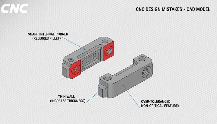
By systematically reviewing designs for these mistakes before sending out RFQs, you protect your budget and your schedule. More importantly, you build a better relationship with machining partners, because they can focus on delivering precision and reliability instead of fighting avoidable design issues.
Prototype vs Production CNC Machining for Robotics Components
Robotics projects rarely move directly from concept to mass production. Most systems evolve through prototypes, pilot builds, and gradual scaling, with design changes along the way. CNC machining supports every stage of this journey by offering flexibility early on and stability later, provided you adapt your manufacturing strategy to each phase.
Understanding how prototype, pilot, and production CNC machining differ helps you control cost, shorten development cycles, and avoid process changes that disrupt quality at the worst possible time.
Rapid prototyping for robot design validation
Rapid prototyping with CNC machining allows you to validate real-world behavior long before committing to production volumes. Unlike visual prototypes, CNC machined prototypes reflect true material properties, stiffness, mass, and tolerances, which makes test results meaningful.
During this stage, engineers typically validate:
-
Structural stiffness and vibration response
-
Joint alignment and bearing fits
-
Tool reach, clearances, and collision risks
-
Integration with motors, sensors, and controllers
Because CNC machining does not require permanent tooling, design iterations remain relatively fast. You can revise pocket depths, change rib layouts, or adjust mounting patterns without waiting weeks or months for new molds. This flexibility is especially valuable in robotics, where minor mechanical updates often lead to major gains in accuracy or durability.
Prototype CNC parts may not be cost-optimized, and that is acceptable. The objective is learning, not unit price. Still, working with a CNC supplier who understands robotics helps ensure early designs do not drift into geometries that will later be difficult or expensive to scale.
Pilot builds and bridge production
Pilot builds and bridge production sit between early prototypes and full production. At this stage, designs stabilize, but volumes remain moderate. CNC machining excels here because it offers repeatability without the upfront investment of dedicated tooling.
Typical goals during pilot and bridge phases include:
-
Verifying assembly processes and takt times
-
Confirming tolerance stack-up across multiple units
-
Establishing inspection plans and quality checkpoints
-
Supplying initial customer trials or limited market releases
CNC machining supports process refinement during this phase. Suppliers can introduce dedicated fixtures, improve tool paths, and reduce cycle time while preserving flexibility for late-stage design updates. For robotics OEMs and integrators, this approach reduces risk as demand ramps up gradually rather than all at once.
From a sourcing perspective, bridge production also reveals whether a supplier can maintain consistency across multiple batches. Stable quality and predictable lead times here are strong indicators that long-term production will succeed.
When to combine CNC machining with die casting?
As robotics platforms mature and volumes increase, CNC machining alone may no longer offer the most cost-effective solution. This is where combining die casting with CNC machining becomes attractive for certain components.
Die casting works well for parts with complex external shapes produced in high volumes, such as housings, brackets, or enclosures. However, die casting alone rarely meets the precision requirements of robotics. Critical features still require CNC finishing, including:
-
Bearing seats and precision bores
-
Datum faces and alignment surfaces
-
Threaded holes and sealing interfaces
This hybrid approach allows you to amortize tooling cost over larger volumes while preserving the accuracy that robotic systems demand. The break-even point varies by part complexity and material, but many robotics producers consider die casting when annual volumes reach several thousand units and designs are stable.
The key risk lies in timing. Moving to die casting too early locks in geometry and reduces flexibility. Moving too late leaves cost savings unrealized. CNC machining provides continuity across this transition, because the same functional features and inspection logic carry forward from prototypes into cast-and-machined parts.
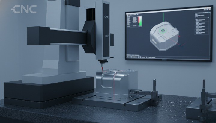
Quality Control for CNC Machined Robotics Components
Quality control for CNC machining and die casting is not just about catching bad parts at the end of the line. It is about building a stable process that delivers predictable geometry, surface condition, and material properties over time. Robots operate in closed-loop systems, but their performance still depends on mechanical consistency. When quality drifts, calibration becomes fragile, maintenance increases, and field failures erode trust with end users.
A structured quality approach for robotics parts usually combines three pillars: First Article Inspection (FAI) to validate the design and process, in-process and final inspection to keep production on target, and traceability to understand how parts behave across global supply chains. Together, these elements turn CNC machining from a black box into a controlled, auditable system.
First Article Inspection (FAI) for robot parts
First Article Inspection is the point where a new or significantly changed robot part meets reality. An FAI verifies that the CNC process can produce one complete part that matches the drawing, material, and functional requirements before you release the design for routine production. Standards such as AS9102, widely used in aerospace, formalize this concept and are increasingly referenced by other high-reliability industries.
For robotics components, a robust FAI typically covers:
-
Dimensional checks on all critical and representative features
-
Verification of GD&T requirements tied to datums and kinematic references
-
Confirmation of material grade, hardness, and surface treatments
-
Documentation of setups, tooling, and measurement methods used
The value of FAI is not just in saying “pass” or “fail.” It creates a baseline that design, manufacturing, and quality can all reference when there are later questions about performance. If a robot shows unexpected drift or vibration in the field, you can compare current parts against the original FAI to see whether the process or the design has changed.
In-process and final inspection strategies
Once FAI confirms the process, you still need ongoing control to keep production within limits. For CNC machined robotics components, in-process and final inspection strategies should be designed around risk and function, not around checking every dimension on every part.
Effective in-process inspection might include:
-
Operator checks of key dimensions using calipers, micrometers, or bore gauges at defined intervals
-
Statistical sampling of critical features to monitor trends rather than single values
-
Tool wear monitoring and offset adjustments tied to measured data instead of fixed time intervals
Final inspection then verifies that the batch meets your contractual and functional requirements. This stage often focuses on:
-
Critical GD&T callouts that affect robot accuracy and repeatability
-
Surface finish and cosmetic criteria where the robot will be visible to end users
-
Fit checks with mating parts or gauges that simulate real assembly conditions
For higher-risk parts, many teams adopt elements of statistical process control (SPC). Tracking key dimensions over time helps you detect drift before it reaches specification limits, reducing scrap and rework. Robotics programs benefit from this approach because small, consistent variations matter more when multiple axes and joints compound their errors.
Traceability and consistency in global robotics supply chains
As robotics companies scale, components often move between factories, countries, and suppliers. Traceability becomes essential to maintain consistency and understand how parts behave over time and across locations. Without it, you may see performance differences between robots built in different plants and struggle to identify the root cause.
Traceability for CNC machined robotics components typically includes:
-
Lot or batch numbers linked to material certificates and machining records
-
Serialized parts for high-value or safety-critical components
-
Retained inspection data tied to specific batches or serials
-
Clear change management records when drawings, materials, or processes are updated
International standards such as ISO 9001 emphasize documented processes, change control, and record retention as foundations for consistent quality across the supply chain. When you apply these principles to robotics components, you gain the ability to correlate field performance with specific suppliers, materials, or process changes, rather than relying on anecdotal feedback.
For global OEMs and integrators, strong traceability also supports regulatory and customer expectations in sectors such as automotive, medical, or food handling, where robots operate in audited environments. It allows you to answer difficult questions about “what changed and when” with data instead of speculation, which is invaluable during investigations or product improvements.
When FAI, in-process control, and traceability work together, quality becomes a managed process rather than an inspection bottleneck. That stability is a prerequisite for choosing and trusting CNC machining suppliers for critical robotics components across multiple programs and regions.
How to Choose a CNC Machining Supplier for Robotics Components?
Choosing the right CNC machining supplier for robotics components is a strategic decision, not just a price comparison. The best partner combines technical capability, real robotics experience, and a proven ability to grow with your program from first prototypes to stable production. If you select only on unit cost, you often pay later in delays, quality issues, or redesign work.
A strong supplier helps you avoid these traps by understanding how robot parts behave in assemblies, suggesting practical DFM improvements, and maintaining consistent quality across batches and years. The following sections give you a structured way to evaluate potential partners and separate general job shops from suppliers who truly support robotics.
Evaluating technical capability and robotics experience
The first filter for any CNC machining supplier is basic technical capability. They must be able to hold the tolerances, materials, and surface finishes your robotics components require. For robotics, that usually means stable control of bearing fits, datum faces, and complex multi-face parts, not just simple brackets.
Key questions to explore include:
-
What machine types do they operate (3-axis, 4-axis, 5-axis, turning centers) and how do these match your part geometries?
-
Which materials do they routinely machine, especially in aluminum, stainless steel, and engineering plastics?
-
What measurement equipment do they use for critical features, such as CMMs, bore gauges, and surface roughness testers?
Beyond machines and gauges, robotics-specific experience is a crucial differentiator. Suppliers who have produced robot arms, joint housings, EOAT, or precision fixtures understand how small shape or tolerance changes ripple through kinematic chains. They recognize why a mounting face flatness callout or a concentricity requirement matters and will treat these features accordingly.
When you review portfolios or case studies, look for evidence of similar parts and assemblies, not just generic “precision machining” claims. A supplier who has already navigated robot alignment issues or EOAT changeover requirements will likely need less explanation and will make fewer assumptions that put your projects at risk.
Engineering support and DFM collaboration
Technical capability alone is not enough if the supplier operates as a “build to print only” vendor. Robotics projects benefit most from suppliers who engage as engineering partners, offering DFM input, manufacturability checks, and clear feedback when drawings create risk or cost.
Effective engineering support might include:
-
Early review of CAD models and drawings to highlight thin walls, deep pockets, or ambiguous GD&T
-
Practical suggestions to standardize threads, fillets, and tolerances without compromising robot performance
-
Feedback on fixture concepts or datum choices that affect repeatability during machining and inspection
This collaboration helps you avoid late-stage surprises, such as finding out a critical joint housing requires unplanned 5-axis operations or that tool access is impossible without redesign. It also prevents silent compromises, where a supplier modifies features informally to make them “easier to machine,” potentially undermining your design intent.
A simple way to gauge DFM maturity is to observe how a supplier responds when you send a challenging part. Do they return a quote only, or do they also raise specific questions and suggestions? Suppliers who take the time to ask targeted technical questions usually care about long-term fit, not just winning a single order.
Scaling from prototype to long-term production
Robotics components place unique demands on scaling because product architectures evolve while customers expect stable performance and availability. Your ideal CNC supplier can handle small prototype batches, support pilot runs, and then ramp to steady production without constant requalification or quality swings.
When you evaluate scalability, consider:
-
Can the supplier reserve or add machine capacity as your program grows, especially for recurring robot platforms?
-
Do they have a clear process for documenting setups, tooling, and inspection so that repeat orders match earlier deliveries?
-
How do they handle engineering changes, revision control, and controlled phase-out of old designs?
You can also test scalability by examining how they manage families of similar parts. Robotics programs often include multiple variants of arms, joints, or EOAT with shared interfaces. A strong supplier will propose common fixture strategies or standardized inspection plans to reduce changeover time and improve consistency across variants.
Finally, scaling is not only about quantity; it is about time and geography. If you plan to build robots in different regions or add assembly locations, ask how the supplier supports global logistics, batch traceability, and stable lead times. The best CNC partners for robotics components see your roadmap as a shared plan and can explain how their organization will keep quality and delivery aligned with it over the long term.
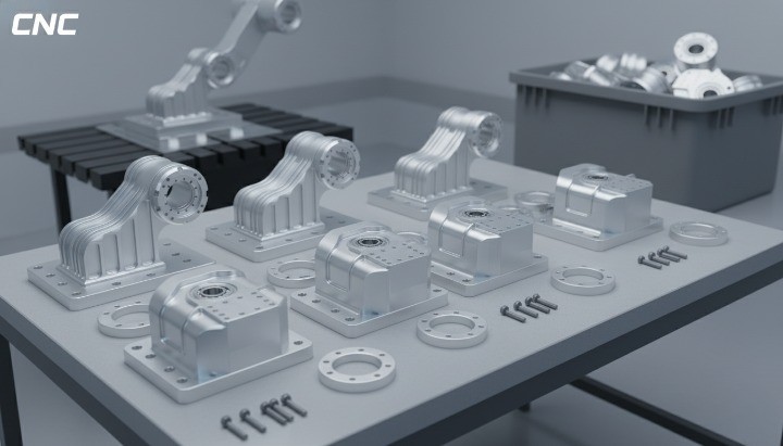
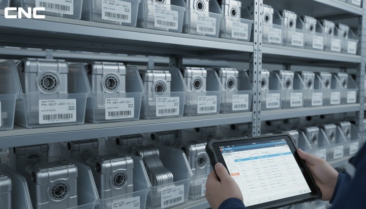
[Image placeholder — place here] Image description: Racks of serialized CNC machined robot components ready for shipment, indicating scalable production capability. Alt text: Scalable CNC machining production of serialized robotics components ready for global supply*
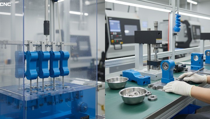
CNC Machining Services for Robotics Components
CNC machining services for robotics components must go beyond basic part production. Robotics programs demand precision, consistency, and engineering awareness across multiple processes, often within tight development schedules. A capable CNC partner integrates machining, finishing, inspection, and sub-assembly into a controlled workflow that supports both innovation and scale.
This section outlines the core machining capabilities and service elements that matter most when sourcing CNC machined robotics components for global use.
CNC milling and turning capabilities for robot parts
Robotics components often feature complex geometries, multiple reference surfaces, and tight tolerance relationships that require more than basic 3-axis machining. Advanced CNC milling and turning capabilities are essential to ensure accuracy and repeatability across all functional interfaces.
CNC milling supports the production of robot bases, arms, brackets, EOAT bodies, and structural plates with controlled flatness and perpendicularity. Multi-axis milling allows simultaneous machining of multiple faces, reducing re-clamping errors and improving geometric consistency. This is particularly important for joint housings and adapter plates where face-to-face relationships define axis alignment.
CNC turning plays a key role in rotational and cylindrical robot components. Shafts, bushings, spacers, hubs, and bearing-related parts benefit from turning operations that deliver excellent roundness and surface finish. When milling and turning are combined in mill-turn centers, suppliers can machine complex parts in a single setup, minimizing tolerances stack-up and inspection variability.
For robotics programs, the real advantage lies in process control rather than machine count. Consistent fixturing, documented setups, and validated tool paths ensure that parts produced months apart still assemble and perform the same way.
Material options, surface finishes, and sub-assembly
Robotics systems rely on a combination of materials and finishes to meet mechanical, environmental, and aesthetic requirements. CNC machining services should therefore cover a broad material portfolio and integrate finishing processes without breaking traceability or quality control.
Typical material support includes:
-
Aluminum alloys for lightweight structural and mounting components
-
Carbon and alloy steels for high-load interfaces and drive elements
-
Stainless steels for corrosive or washdown environments
-
Engineering plastics for guides, spacers, and electrically insulating parts
Surface finishing extends functional performance. Anodizing improves corrosion resistance and wear behavior on aluminum. Plating and passivation protect steel components. Controlled surface roughness ensures reliable sliding, sealing, or clamping depending on application. When finishing stays within the same quality system as machining, dimensional changes remain predictable and documented.
Sub-assembly services further simplify robotics sourcing. Installing threaded inserts, pressing bearings, mounting pins, or assembling small modules shifts work away from the robot integrator’s floor. This reduces handling risk and ensures critical fits are completed under controlled conditions by trained technicians.
Supporting global robotics OEMs and system integrators
Global robotics OEMs and system integrators operate across regions, timelines, and customer requirements. CNC machining services must therefore support international coordination, communication, and quality expectations, not just local production.
Key support elements include:
-
Clear documentation in English, including drawings, inspection reports, and change records
-
Stable packaging and logistics processes suitable for long-distance shipping
-
Batch-level traceability that remains intact across borders and warehouses
-
Flexibility to handle mixed orders of prototypes, spares, and production parts
For system integrators, responsiveness matters as much as price. Automation projects often involve tight commissioning windows where missing hardware can delay entire production lines. Suppliers that understand this reality prioritize lead-time reliability and proactive communication when schedules shift.
For OEMs, long-term consistency is paramount. Robotics platforms may ship for years with evolving variants. CNC partners who invest in fixture standardization, revision control, and shared process knowledge become extensions of the OEM’s manufacturing organization. This relationship reduces lifecycle cost and stabilizes product performance in the field.

Conclusion
CNC machining for robotics components provides the mechanical foundation that makes accurate, repeatable, and durable robotic systems possible. From structural bases and joints to end-of-arm tooling and sensor mounts, CNC machining connects design intent with real-world performance through precise geometry, controlled tolerances, and stable materials. When engineers align material selection, GD&T, DFM principles, and quality control around CNC processes, robots become easier to assemble, calibrate, and maintain over their full service life.
For robotics OEMs, system integrators, and engineering teams, the value of CNC machining goes beyond individual parts. It supports predictable scaling from prototypes to production, reduces integration risk, and enables long-term supply consistency.